


The Role of Standardized Gauging in Ensuring Safety and Interoperability of Plugs and Sockets
The global marketplace for electrical wiring devices, specifically plugs and socket-outlets, demands an unwavering commitment to safety and performance. A critical component in upholding these standards is the precise verification of dimensional compliance. Dimensional inaccuracies, even those measured in fractions of a millimeter, can lead to hazardous conditions including electric shock, poor electrical contact leading to overheating, and mechanical failure. To mitigate these risks, standardized test gauges, such as the one specified in UL 498 Figure 109.1, serve as the definitive arbiters of conformance. These instruments provide an objective, repeatable methodology for manufacturers and certification bodies to validate that a product’s design adheres to the stringent requirements set forth by safety standards.
This article examines the technical specifications, application principles, and critical importance of the UL 498 Figure 109.1 test gauge. Furthermore, it will explore the implementation of this standard through modern testing equipment, with a specific focus on the LISUN Gauges for Plugs and Sockets, which are engineered to deliver the precision and reliability required for contemporary compliance testing.
Anatomizing the UL 498 Figure 109.1 Test Gauge
The UL 498 standard, governing the safety of attachment plugs and receptacles, dedicates significant attention to physical dimensions. Figure 109.1 illustrates a specific gauge designed to verify the configuration of slot openings in receptacle faces. This gauge is not a simple measuring tool like a caliper; it is a “go/no-go” gauge, a fundamental concept in dimensional metrology. Its purpose is binary: to confirm whether a critical feature falls within a predefined tolerance zone without providing a specific quantitative measurement.
The gauge itself is a precision-machined artifact, typically fabricated from hardened steel or another durable, dimensionally stable material resistant to wear. Its design incorporates two primary features: a “GO” member and a “NO-GO” member. The GO member, which must fit into the receptacle slot with a specified force, verifies that the slot is sufficiently wide and unobstructed to accept a corresponding plug blade. The NO-GO member, which must not fit into the slot under its own weight or with minimal force, ensures the slot is not excessively wide. An overly wide slot presents a significant shock hazard, as it could allow unintended access to live electrical parts, such as a child’s finger or a foreign object.
The dimensional tolerances specified for the gauge in Figure 109.1 are exceptionally tight, often in the range of a few thousandths of an inch. This precision is non-negotiable, as the gauge itself becomes the reference standard against which millions of electrical devices are judged. The geometry of the gauge also accounts for factors such as chamfers and radii at the entry of the receptacle slots, ensuring that the test accurately simulates the insertion of a real plug blade under safe conditions.
The Critical Function of Dimensional Verification in Connector Safety
The consequences of non-conforming receptacle slot dimensions are severe and multifaceted. From an electrical safety perspective, the primary hazard is the increased risk of electric shock. If the slot opening is too large, the standard-mandated shutters or barriers within the receptacle may fail to function correctly, or a user may be able to insert a conductive object that makes contact with an energized terminal. The NO-GO gauge directly tests this safety-critical aspect.
From an electromechanical performance standpoint, improper slot dimensions can lead to poor contact between the plug blades and the receptacle contacts. A slot that is too narrow may cause difficulty in inserting the plug, leading to user frustration and potential damage to the plug or receptacle. More dangerously, a slot that is too wide can result in a loose connection. A loose connection has high electrical resistance, which in turn generates excessive heat under load due to I²R heating. This overheating can degrade the insulation of the wiring device, pose a fire risk, and ultimately lead to connection failure. The GO gauge ensures that a standard plug can be inserted to the proper depth, establishing a secure and low-resistance electrical path.
Furthermore, dimensional consistency is paramount for interoperability. Consumers and businesses rightly expect that a plug conforming to a specific national standard (e.g., NEMA 5-15) will fit securely into any receptacle claiming the same rating. The UL 498 Figure 109.1 gauge, and others like it, are the tools that enforce this universal compatibility, preventing market fragmentation and ensuring that safety is not compromised by manufacturing variances.
Operational Methodology for Receptacle Slot Compliance Testing
The application of the UL 498 Figure 109.1 gauge follows a strict procedural protocol to ensure test repeatability and accuracy. The testing is typically performed on a sample of receptacles that have undergone conditioning, such as exposure to heat or mechanical stress, as required by the standard. The test procedure is sequential and unambiguous.
First, the GO member of the gauge is carefully aligned with the slot of the receptacle. A calibrated force, not exceeding the value specified in the standard (often delivered by a dead-weight force gauge), is applied to attempt to insert the GO member. For the receptacle to pass this phase, the GO member must enter the slot to its full depth without binding or requiring excessive force. This confirms that the minimum slot width and entry geometry are correct.
Second, the NO-GO member is presented to the same slot. This member is applied under its own weight or with a minimal, specified force. The receptacle passes only if the NO-GO member cannot be inserted into the slot. Any entry of the NO-GO member constitutes an immediate failure, as it indicates that the slot opening exceeds the maximum permissible width, creating an unacceptable shock hazard.
This binary testing approach eliminates subjectivity. The outcome is not a matter of interpretation; the receptacle either passes both criteria or it fails. This makes the gauge an ideal tool for use on production lines for quality control checks and in certification laboratories for type-test approval.
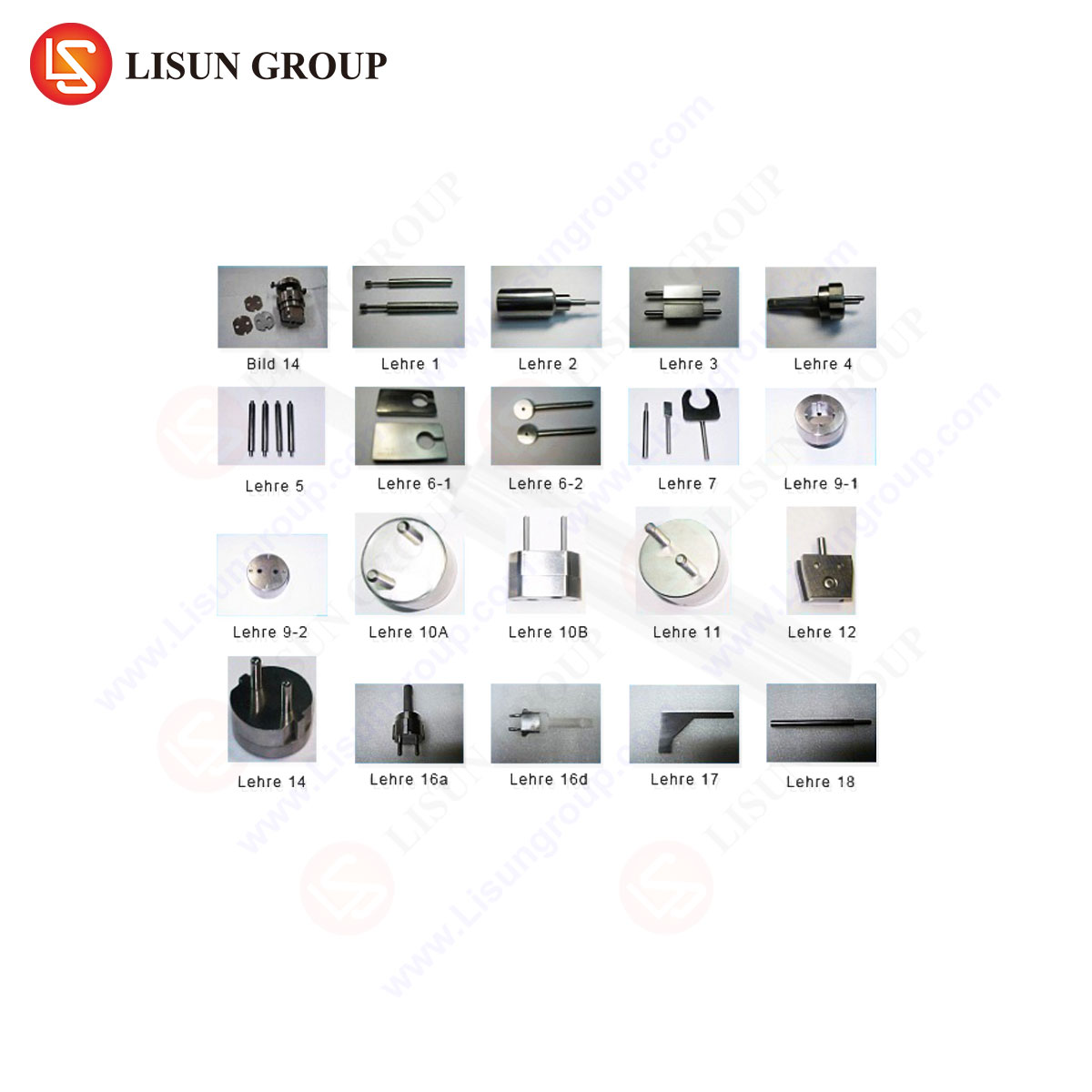
LISUN Gauges for Plugs and Sockets: Precision Engineering for Modern Compliance
To meet the exacting demands of standards like UL 498, testing equipment must be manufactured to a level of precision that exceeds the tolerances of the products it is designed to evaluate. LISUN Gauges for Plugs and Sockets are engineered specifically for this purpose, providing certification laboratories and quality assurance departments with reliable, traceable, and durable tools for compliance verification.
The LISUN gauge system designed for UL 498 Figure 109.1 testing is typically constructed from high-carbon, high-chromium tool steel that has been heat-treated to achieve a high surface hardness (often exceeding HRC 60). This treatment ensures exceptional wear resistance, preserving the critical dimensions of the gauge over thousands of test cycles and maintaining calibration integrity. The surface finish is meticulously controlled to a low roughness average (Ra), preventing false failures due to friction and ensuring smooth, consistent insertion.
Key specifications for a LISUN UL 498 Figure 109.1 Gauge may include:
- Material: GCr15 (AISI 52100) bearing steel or equivalent.
- Hardness: 60-63 HRC.
- Surface Finish: Ra ≤ 0.4 µm.
- Dimensional Tolerance: ±0.005 mm for critical features.
- Geometry Tolerance: Parallelism and perpendicularity within 0.01 mm.
- Traceability: Each gauge is supplied with a certificate of calibration traceable to national metrology institutes.
Beyond the gauge itself, LISUN systems often incorporate ergonomic handles and clear markings for easy identification of the GO and NO-GO ends, reducing operator error. For high-volume testing environments, fixtures may be available to hold the receptacle securely and guide the gauge precisely, further enhancing repeatability.
Comparative Analysis of Gauge Performance and Long-Term Reliability
The performance of a test gauge is ultimately defined by its accuracy and its longevity. In a competitive landscape, the advantages of a precision-engineered gauge like those from LISUN become evident when compared to lower-cost alternatives. The primary differentiator lies in material science and manufacturing quality control.
A gauge manufactured from inferior materials or without proper heat treatment will experience rapid wear at its edges and contact surfaces. This wear gradually alters its dimensions, causing a once-accurate gauge to reject conforming products (a false negative) or, more dangerously, accept non-conforming products (a false positive). The latter scenario poses a severe risk as it allows unsafe products to enter the market. The use of hardened tool steel in LISUN gauges directly combats this dimensional drift, ensuring that the gauge remains within its specified tolerance for a significantly longer operational lifespan.
Furthermore, the precision grinding and lapping processes used in manufacturing high-end gauges ensure that the geometric form—the straightness, flatness, and corner radii—is perfectly maintained. A gauge with minor imperfections in its geometry may not accurately simulate the insertion of a standard plug blade, leading to inconsistent test results. The rigorous quality assurance protocols applied to LISUN products guarantee that each gauge is a faithful physical representation of the dimensional requirements set forth in the standard, providing confidence in every test outcome.
Integration of Standardized Gauging in Quality Assurance Workflows
The use of the UL 498 Figure 109.1 gauge is not an isolated activity but a integrated component of a comprehensive Quality Assurance (QA) and Type-Testing regimen. In a manufacturing context, these gauges are deployed at various stages. They are used for first-article inspection to validate new mold tools or production lines. They are also employed for statistical process control (SPC), where periodic checks are performed on samples taken from the production line to monitor for any drift in the molding or stamping processes that create the receptacle face.
In third-party certification laboratories, such as those affiliated with UL, Intertek (ETL), or TÜV, the gauge is a fundamental tool for initial product certification. A product sample cannot receive a safety certification mark unless it successfully passes the gauge tests, along with a battery of electrical, mechanical, and environmental tests. The objective nature of the gauge test provides a clear and defensible pass/fail criterion for the certification engineer.
The data derived from gauge testing can also be fed back into the product design process. If a design consistently passes gauge tests with minimal margin, it may indicate a need for a design revision to create a more robust manufacturing tolerance window, thereby improving yield and long-term reliability. Thus, the gauge serves not only as a compliance tool but also as a valuable source of engineering intelligence.
Frequently Asked Questions (FAQ)
Q1: How often should a UL 498 Figure 109.1 test gauge be calibrated?
The calibration interval depends on usage frequency and the quality of the gauge. For a gauge used daily in a quality control lab, an annual calibration is a common industry practice. However, if the gauge is dropped or shows signs of wear, it should be calibrated immediately. LISUN recommends a maximum interval of 12 months and provides calibration services traceable to NIST or other national standards.
Q2: Can a single gauge be used for testing different receptacle configurations, like a NEMA 5-15 and a NEMA 5-20?
No. Each receptacle configuration defined by a standard (NEMA 5-15, 5-20, 6-15, etc.) has unique slot dimensions and spacings. Each configuration requires its own dedicated set of GO/NO-GO gauges, which are designed to the specific dimensions outlined in the applicable standard. Using an incorrect gauge will yield meaningless and potentially dangerous results.
Q3: What is the proper procedure if a receptacle fails the GO gauge test?
A failure of the GO gauge test indicates the slot is too narrow or obstructed. The receptacle should be rejected. The cause of the failure must be investigated, which could include issues with the injection molding tool, flash (excess material) in the slot, or a malfunctioning shutter mechanism inside the receptacle. The production process should be halted until the root cause is identified and corrected.
Q4: Besides the slot width gauge in Figure 109.1, what other gauges are required for a complete receptacle test?
UL 498 specifies several other gauges for a full assessment. These include, but are not limited to, gauges for measuring plug blade dimensions (to ensure they fit the slots), a gauge for testing the grounding pin slot, and a “drop test” gauge to verify the effectiveness of the safety shutters. A complete test set encompasses all gauges necessary to verify every critical dimension of the plug and receptacle system.
Q5: Why is the material hardness of the gauge so critical?
Hardness is directly correlated with wear resistance. During testing, the steel gauge repeatedly contacts the typically plastic or thermoplastic receptacle. A soft gauge will wear down quickly, its dimensions becoming smaller than specified. This would cause the gauge to falsely pass receptacles with slots that are actually too narrow (a GO gauge that has worn down) or too wide (a NO-GO gauge that has worn down), compromising safety. High hardness ensures dimensional stability over the gauge’s lifetime.