


A Critical Examination of the UL498 Figure 111.2 Test Blade and Its Role in Ensuring Electrical Safety Compliance
Introduction: The Imperative of Standardized Mechanical Testing
Within the rigorous framework of electrical safety certification, the evaluation of mechanical integrity is as critical as the assessment of electrical performance. For receptacles and connectors, one of the most definitive mechanical tests involves verifying the ability of protective shutters or the receptacle contacts themselves to resist intrusion by foreign objects. This test is not merely a procedural formality; it is a direct safeguard against electric shock hazards, particularly for children. The standard referenced under UL 498, Figure 111.2, specifies the precise dimensional and material requirements for a test blade used to assess this protective capability. This article provides a comprehensive technical analysis of the UL498 Figure 111.2 test blade, its application within compliance testing protocols, and the instrumental role of specialized gauging systems, such as those manufactured by LISUN, in executing these evaluations with precision and repeatability.
Dimensional Specifications and Material Conformance of the Test Blade
The efficacy of any compliance tool is rooted in its adherence to published specifications. The blade defined in UL 498, Figure 111.2, is characterized by a set of exacting dimensional tolerances. The primary probing element is a flat, rectangular blade with a specified thickness, width, and length. Crucially, the leading edge is radiused to a defined dimension, preventing sharp edges that could cause damage not representative of a typical foreign object. The blade is mounted on a handle of prescribed dimensions to ensure consistent application of force and angle during testing.
Material selection is equally mandated. The standard typically requires the blade to be constructed from a hardened steel, such as tool steel, with a specified Rockwell hardness value. This ensures the blade does not deform during testing, which would invalidate the results by presenting a non-conforming probe geometry. The material’s rigidity guarantees that any deflection or access granted during the test is a function of the receptacle’s design failure, not the tool’s compromise. Even minor deviations in the blade’s thickness or hardness can lead to false positives or negatives, rendering a certification test invalid and potentially allowing unsafe products to reach the market.
The Mechanical Testing Principle: Simulating Hazardous Intrusion
The fundamental testing principle is one of simulated intrusion under defined conditions. For a standard 15A or 20A, 125V receptacle incorporating safety shutters, the test procedure involves applying the Figure 111.2 blade to the shutter-protected slot openings with a specified force, typically 35 Newtons, and in a prescribed sequence. The objective is to determine whether the blade can bypass the shutter mechanism and make contact with the live electrical parts within.
The test evaluates the shutter’s design robustness. A compliant shutter mechanism must not open to permit access of the test blade when it is applied alone to a single opening. This often requires a shutter design that is actuated only by the simultaneous insertion of both blades of a plug, or by a specific mechanical interlock. The Figure 111.2 blade, representing a single, rigid object like a key or a hairpin, must be resisted. The test is conducted at various angles and orientations as stipulated by the standard to account for real-world misuse scenarios. The pass/fail criterion is binary: if electrical contact is established between the test blade and the live contact inside the receptacle, the sample fails.
Instrumentation for Precision: The Role of the LISUN Gauges for Plugs and Sockets
Executing this test with manual tools introduces significant variables: inconsistent application of force, unmeasured angle of entry, and potential for operator-induced error. This is where dedicated test apparatus becomes indispensable. The LISUN Gauges for Plugs and Sockets system provides a calibrated, instrumented solution for performing the UL498 Figure 111.2 test, among other critical dimensional and mechanical checks.
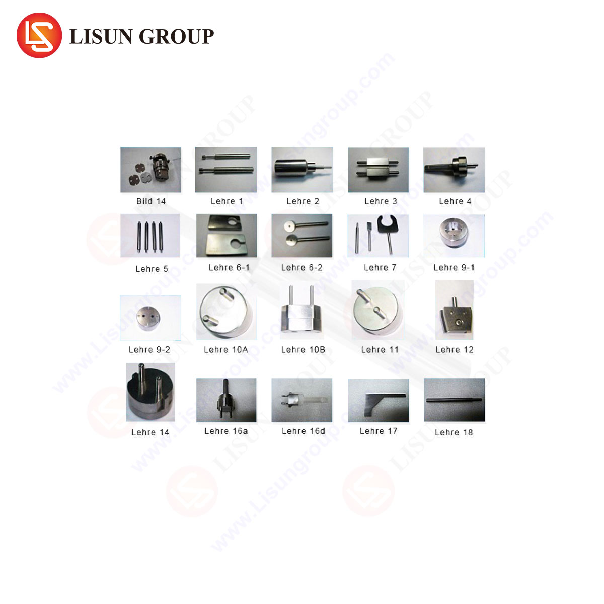
The LISUN system typically incorporates a precision-machined test blade fixture that holds the Figure 111.2 blade in strict conformance to the standard’s geometry. This fixture is mounted on a force application mechanism, often a push-pull gauge or a motorized actuator, which can apply the exact force required (e.g., 35 N ± 2%) at a controlled rate. The apparatus ensures the blade’s approach vector is perpendicular to the receptacle faceplate, eliminating angular variables. Furthermore, the system includes a sensitive electrical continuity circuit. When the test blade makes contact with the receptacle’s internal live part, the circuit closes, triggering an immediate visual and audible alarm, and often logging the event with a timestamp.
Technical Specifications and Operational Advantages of the LISUN System
The LISUN gauging system is engineered to meet the exacting demands of third-party testing laboratories, quality assurance departments at major manufacturers, and standards certification bodies. Key specifications and advantages include:
- Calibrated Force Application: Integrated digital force gauge with programmable setpoints and real-time readout, ensuring the mandated force is applied accurately and repeatably across hundreds of test cycles.
- Standard-Compliant Tooling: A full suite of interchangeable test probes, including the UL498 Figure 111.2 blade, NEMA configuration blades, and IEC standard pins, all manufactured to the geometric and material specifications of the relevant standards (UL, IEC 60884, AS/NZS, etc.).
- Automated Test Sequencing: Programmable logic controllers allow for the automation of complex test sequences, such as applying the blade to each slot in a specific order with dwell times, increasing throughput and eliminating operator sequencing errors.
- Integrated Detection Circuitry: A high-sensitivity, low-voltage detection circuit identifies electrical contact without presenting a shock hazard to the operator. The system differentiates between contact with the shutter and contact with the live terminal.
- Data Logging and Reporting: RS-232 or USB interfaces enable the export of test data—including force applied, pass/fail status, and test duration—for traceability and quality records, essential for ISO 17025 accredited labs.
The competitive advantage of such a system lies in its reduction of measurement uncertainty. By removing operator influence from the force and angle variables, the LISUN apparatus provides objective, repeatable, and auditable data. This accelerates the design validation process for manufacturers, who can obtain reliable feedback on shutter prototypes, and provides certifiers with unambiguous evidence of compliance or non-compliance.
Industry Application and Integration in the Product Development Lifecycle
The use of the UL498 Figure 111.2 test blade and its automated counterparts is integrated throughout the product lifecycle of plugs, sockets, and power connectors. During the Design & Prototyping phase, engineers use the test to iteratively validate shutter mechanisms. Early failure informs redesign before tooling is committed. In the Pre-compliance & Qualification phase, manufacturers perform exhaustive testing on pre-production samples to ensure a high probability of passing formal certification by a Nationally Recognized Testing Laboratory (NRTL). The Production Quality Assurance phase involves statistical sampling of production units. Automated systems like the LISUN gauges allow for rapid, reliable testing on the factory floor, ensuring ongoing production consistency. Finally, in Certification Testing at an NRTL, the test is performed as a mandatory part of the safety evaluation, often using similarly sophisticated apparatus to ensure definitive results.
Broader Context: The Test Blade within the Ecosystem of Safety Standards
The UL498 Figure 111.2 blade is not an isolated requirement. It exists within a comprehensive suite of tests for receptacles, including contact retention tests, overload tests, and dielectric withstand tests. Its specific role is to address a particular hazard scenario—probing by a single rigid object. Other test probes, such as the smaller “articulated probe” defined in other standards (like IEC 60884), address different hazard scenarios, such as the entry of small, flexible objects. A robust safety standard employs a matrix of tests, each with a tool designed to simulate a distinct real-world threat. Understanding the specific failure mode each test blade is designed to provoke is essential for engineers designing protective features.
Conclusion
The UL498 Figure 111.2 test blade embodies the principle that safety standards must be enforceable through objective, repeatable physical tests. Its precise geometry and material properties translate a written safety requirement—that shutters must resist intrusion—into a quantifiable mechanical experiment. The evolution from manual application to instrumented systems, such as the LISUN Gauges for Plugs and Sockets, represents the maturation of compliance verification into a precise engineering discipline. These systems ensure that the critical barrier between user and electrical energy is evaluated with the highest degree of technical rigor, ultimately contributing to the prevention of electrical injuries and upholding the integrity of the safety certification ecosystem.
FAQ Section
Q1: Can the LISUN system be configured for standards other than UL 498?
Yes. The system is modular, with interchangeable probe libraries. It can be configured with test blades and pins for IEC 60884 (international), AS/NZS 3112 (Australia/New Zealand), GB 2099.1 (China), and other major national standards, making it suitable for global manufacturers targeting multiple markets.
Q2: How often should the test blade and force gauge be calibrated?
Calibration intervals should be determined based on usage frequency, laboratory accreditation requirements (e.g., ISO 17025), and manufacturer recommendations. Typically, the force transducer requires annual calibration by an accredited metrology lab. The physical test blades should be periodically verified for dimensional wear, especially on leading edges and thickness, using precision micrometers.
Q3: What is the consequence of using a non-conforming or worn test blade?
Using a blade that is even slightly undersized in thickness due to wear can cause a receptacle to falsely pass the test, as the shutter may resist a thinner object but fail with the correct one. Conversely, a blade with a burr or damage may mechanically jam or damage the shutter, causing a false failure. Both scenarios compromise the validity of certification and product safety.
Q4: Does the system test both energized and de-energized receptacles?
The standard mechanical intrusion test using the Figure 111.2 blade is performed on a de-energized, isolated receptacle sample. The electrical detection circuit within the LISUN system uses a low-voltage, low-current signal solely to detect physical contact between the blade and the internal contact metal. The receptacle is not connected to line voltage during this test.
Q5: Can the apparatus simulate the simultaneous insertion of a plug to test shutter actuation?
Advanced versions of plug and socket test systems often include additional fixtures and programmable axes that can simulate the simultaneous, parallel insertion of two or more probe blades (simulating a plug’s live and neutral pins) to positively test the correct actuation of the shutter. This is a separate but complementary test to the single-blade intrusion test.