


A Technical Analysis of Dimensional Verification for BS 546 Plugs and Sockets via GO/NO-GO Gauging
Introduction to Dimensional Conformance in Electrical Accessories
The safe and reliable operation of any electrical accessory is fundamentally predicated upon its adherence to precisely defined dimensional tolerances. This is particularly critical for plugs and sockets conforming to BS 546, a standard historically significant in numerous Commonwealth nations and still specified in specialist industrial, commercial, and legacy installations. Dimensional non-conformance in these components can lead to a cascade of failure modes: poor electrical contact resulting in overheating, insecure mechanical engagement posing arc and shock hazards, and the potential for incorrect insertion of incompatible plug types. Consequently, the verification of manufacturing output against the standard’s geometric requirements is not merely a quality control step but a vital safety imperative. This article provides a detailed examination of the GO gauge specifications as delineated in BS 546 Figure 5, elucidating their design philosophy, application methodology, and their role within a comprehensive quality assurance regimen. The discussion will extend to the practical implementation of these principles using specialized gauging equipment, such as the LISUN Gauges for Plugs and Sockets, to achieve reliable, repeatable verification.
Deconstructing the Functional Purpose of BS 546 Figure 5 GO Gauges
BS 546 Figure 5 specifies the design and critical dimensions for a series of GO gauges used to assess the socket-outlet. It is essential to understand that a GO gauge is a precision instrument designed to test the maximum material condition of a feature. Its function is binary: it must fully enter or engage with the feature under test under a specified, gentle manual force, without binding or requiring excessive pressure. For a BS 546 socket, the GO gauge simulates the “worst-case” permissible plug—one that is at the extreme upper limit of its own specified tolerances but still within the standard’s safe mating envelope. The gauge itself is manufactured to exacting dimensions, representing the virtual boundary of a perfect, maximum-sized plug pin (for pin entry gauges) and the correct spatial relationship between these pins (for the overall gauge body). Successfully accepting the GO gauge demonstrates that the socket’s contact apertures and their alignment are sufficiently large and correctly positioned to accommodate any compliant plug, ensuring mechanical interoperability. The complementary NO-GO gauge, which tests the minimum material condition, is a separate tool used to verify that socket apertures are not excessively large, a condition that could lead to poor contact and overheating.
Critical Dimensional Parameters and Their Safety Implications
The GO gauge detailed in BS 546 Figure 5 is a composite tool that verifies multiple interdependent parameters simultaneously. Its design encapsulates several key checks:
-
Pin Diameter and Shape Conformance: The gauge features pins corresponding to the live, neutral, and earth contacts of the relevant BS 546 type (e.g., Type M 15 A). These pins are manufactured to the maximum allowable diameter as defined for the plug pins in other clauses of BS 546. Their precise cylindrical form and smooth finish are mandatory to ensure the test assesses the socket’s acceptance geometry without interference from gauge imperfections.
-
Pin Center Distance (Pitch Circle Diameter): Perhaps the most critical dimensional check is the verification of the distances between the centers of the socket apertures. Incorrect pitch can prevent insertion of a plug, cause undue stress on plug pins, or misalign the earth pin with its protective guiding channel, compromising earthing integrity before line contacts are made. The GO gauge body maintains the exact maximum material center distances, providing a holistic test of alignment.
-
Aperture Alignment and Angular Position: The gauge ensures the three socket apertures are not only the correct distance apart but are also in the correct angular orientation relative to each other (typically 120° separation for the line and neutral, with the earth at a defined position). Any twisting or misalignment in the socket molding would be detected by the gauge’s failure to seat fully.
-
Depth of Engagement: The length of the gauge pins is designed to verify that the socket contact tubes are of sufficient depth to allow a plug pin to engage fully. Inadequate depth can result in reduced contact area, leading to high resistance and potential thermal failure.
The scientific rationale behind this combined approach is efficiency and functional testing. Rather than verifying each dimension in isolation with calipers or CMMs—a time-consuming process—the GO gauge performs a functional test that simulates the actual mating condition. This aligns with the principle that safety and performance are determined by the assembled state of the components, not just individual measurements.
Operational Methodology and Application of Force in Gauge Testing
The application of GO/NO-GO gauging must follow a strict procedural protocol to ensure validity. The process is deceptively simple but requires trained personnel to avoid false results. For testing a BS 546 socket outlet:
- Gauge Selection: The correct gauge for the socket type (e.g., 5 Amp, 15 Amp Type M, 30 Amp) and rating must be selected.
- Visual Inspection: The gauge must be inspected for damage, wear, or corrosion prior to use. A damaged gauge must be removed from service.
- Application: The gauge is aligned with the socket face and inserted gently. It must enter under its own weight or with a minimal, uniformly applied manual force not exceeding that which would be normally used to insert a plug. The standard often specifies a force, typically applied via a spring balance, to standardize this test.
- Assessment: The gauge is deemed to “GO” if it enters fully and smoothly to its full depth without rocking, binding, or requiring coercion. Any resistance that cannot be attributed to normal friction indicates a failure—the socket apertures may be undersized, misaligned, or out of tolerance.
The specified application force is a critical variable. Excessive force can deform a marginally undersized socket or mask an alignment issue, leading to a false “pass.” Insufficient force may not seat the gauge fully, causing a false “fail.” Therefore, the use of a calibrated force application device or a trained technician with a calibrated “feel” is essential.
Integration of Gauging within a Broader Quality Management System
While GO/NO-GO gauging is a pivotal final inspection step, it represents only one node within a holistic Quality Management System (QMS). Its role is primarily that of attribute sampling—classifying products as conforming or non-conforming to the maximum material boundary. A robust QMS for BS 546 component manufacturing will include:
- Incoming Material Inspection: Verifying the dimensional and material properties of raw brass contacts, thermoplastic compounds, and internal brass components.
- In-Process Controls: Monitoring critical parameters during injection molding (e.g., mold temperature, cooling time, cavity pressure) to prevent drift in aperture dimensions. Dimensional checks on stamped or machined contact assemblies prior to sub-assembly are also crucial.
- Statistical Process Control (SPC): Using variable data measurement tools (e.g., optical comparators, dedicated fixture gauges with dial indicators) on a sampling basis to track process capability (Cp/Cpk) for key dimensions like pin diameter and center distance. This proactive approach identifies trends toward tolerance limits before non-conforming parts are produced.
- Final Inspection & Audit: The application of BS 546 Figure 5 GO/NO-GO gauges serves as the final, functional audit. It may be applied on a 100% basis for high-reliability applications or via Acceptable Quality Level (AQL) sampling plans for bulk production.
- Periodic Gauge Calibration and R&R Studies: All gauges, including GO/NO-GO types, must be part of a metrology management system with regular calibration against master reference standards. Gauge Repeatability and Reproducibility (R&R) studies assess the measurement error introduced by the gauge itself and different operators.
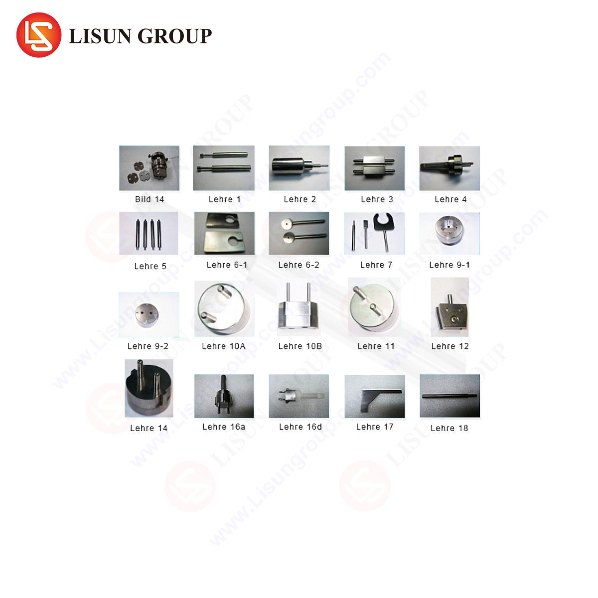
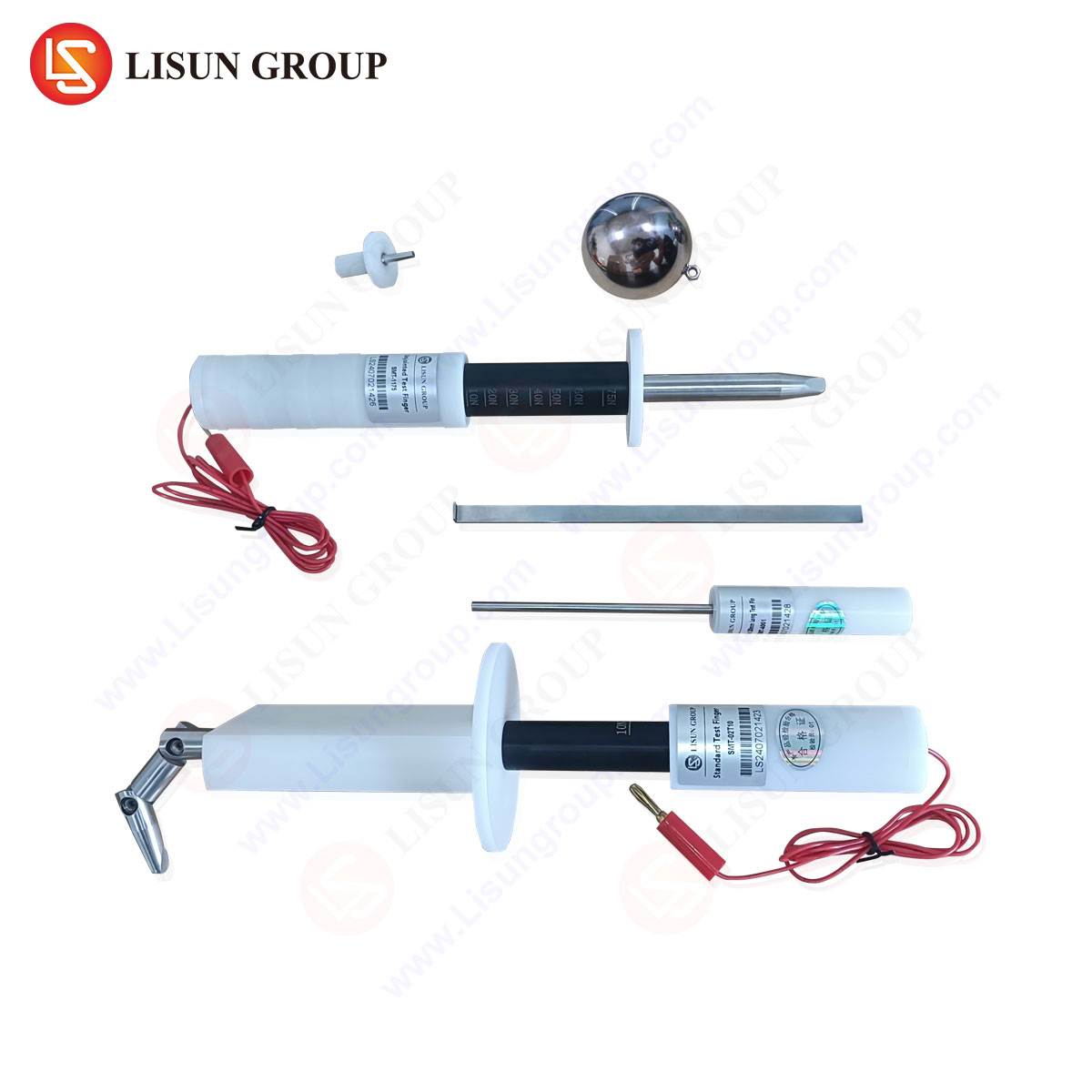
LISUN Gauges for Plugs and Sockets: Engineered for Metrological Precision
Implementing the requirements of BS 546 Figure 5 demands gauging tools of exceptional accuracy, durability, and ergonomic design. The LISUN Gauges for Plugs and Sockets product line is engineered specifically to meet this demand, providing a reliable solution for manufacturers and testing laboratories.
Specifications and Construction: LISUN gauges are manufactured from hardened and stabilized tool steel or high-wear carbide, materials selected for their dimensional stability and resistance to abrasion from repeated insertion into test sockets. The pins are ground and lapped to a micro-finish to achieve the cylindrical form and diameter tolerances mandated by BS 546, often exceeding the standard’s requirements for the gauge itself. The body is designed for a secure grip and clear marking of the gauge type and standard reference.
Testing Principles Embodied: The design of LISUN gauges faithfully embodies the principles of BS 546 Figure 5. Each gauge is a physical manifestation of the maximum material boundary condition for a specific socket type. Their use directly executes the functional test protocol, providing an immediate, unambiguous result regarding the socket’s geometric conformance.
Industry Use Cases: These gauges are deployed across multiple industry segments:
- Manufacturing Quality Control: On production lines for socket-outlet manufacturers, ensuring every batch meets BS 546 dimensional requirements.
- Independent Certification Bodies: Used by test houses (e.g., those affiliated with IECEE CB Scheme) to verify product samples submitted for safety certification.
- Import/Export Compliance: By customs or standards authorities to check shipments of electrical accessories for compliance with national regulations based on BS 546.
- Facility Management and Electrical Contractors: For verifying the correctness of installed sockets in critical environments like data centers, hospitals, or industrial plants where legacy BS 546 systems remain in operation.
Competitive Advantages: The LISUN solution offers distinct advantages in a demanding technical environment. Superior material science extends service life and reduces long-term cost of ownership compared to softer, less durable gauges. Precision manufacturing ensures measurement integrity, reducing the risk of false accepts or rejects. Furthermore, a comprehensive gauge set, covering all common BS 546 types (5A, 15A Type M & D, 30A), provides a unified, consistent testing platform for organizations handling multiple product lines.
Addressing Common Challenges in Socket Dimensional Verification
Several practical challenges can arise during gauge testing. Thermal expansion of plastic socket bodies can cause dimensional shifts; therefore, testing should be conducted at a standardized ambient temperature (e.g., 23°C ±2°C per many standards). Wear debris or molding flash inside contact tubes can impede gauge entry, mimicking a dimensional failure. A strict cleaning protocol for both the gauge and the unit under test is necessary. Operator technique, as previously noted, is a significant variable. Implementing formal training and, where possible, using fixtures to ensure square alignment of the gauge to the socket face can minimize this variation. The LISUN gauge design, with its emphasis on ergonomic handles and clear visual indicators for full engagement, inherently assists in standardizing the operator interface.
Conclusion: The Indispensable Role of Precision Gauging
The GO gauge specifications of BS 546 Figure 5 represent a elegantly practical application of metrological principle to electrical safety. By defining a physical boundary tool, the standard provides a rapid, reliable, and functionally relevant method for assessing the dimensional integrity of socket-outlets. This process is a non-negotiable element in preventing the safety hazards associated with poorly mating electrical connections. The efficacy of this method, however, is entirely dependent on the quality, accuracy, and proper use of the gauging tools themselves. Precision-engineered products, such as the LISUN Gauges for Plugs and Sockets, translate the theoretical requirements of the standard into dependable, day-to-day quality assurance, thereby underpinning the safety and reliability of electrical installations utilizing BS 546 accessories.
FAQ Section
Q1: How frequently should BS 546 GO/NO-GO gauges be calibrated?
A1: Calibration frequency depends on usage intensity and the quality management system requirements. For high-volume production line use, a quarterly or semi-annual calibration schedule is typical. For periodic audit or laboratory use, an annual calibration may suffice. The calibration must be performed by an accredited metrology lab using master reference standards traceable to national measurement institutes.
Q2: Can a socket that passes the GO gauge test still be unsafe?
A2: Yes. The GO gauge test verifies only dimensional conformance to the maximum material condition. It does not test electrical safety parameters such as insulation resistance, dielectric strength, temperature rise, or the integrity of earthing continuity. It also does not verify material quality, creepage and clearance distances, or assembly security. Dimensional gauging is one essential component within a full suite of type tests and routine tests required by the complete BS 546 standard.
Q3: What is the consequence of using a worn GO gauge?
A3: A worn GO gauge will have pins that are undersized due to abrasion. This can lead to a “false accept,” where a socket with apertures that are at or below the minimum allowable size incorrectly passes the test. This is a critical failure mode as it could allow sockets that do not properly engage with compliant plugs to enter the market, creating a safety hazard. Regular inspection for wear and adherence to calibration schedules mitigates this risk.
Q4: Are separate gauges required for the plug component of BS 546 assemblies?
A4: Yes. BS 546 includes separate specifications for gauging plugs (e.g., checking pin diameter, length, and flexibility). These are typically NO-GO gauges for pin diameter (to ensure pins are not too small) and GO gauges for pin spacing. A complete conformance testing regimen requires a full set of gauges for both plugs and sockets.
Q5: How does the LISUN gauge design address operator-induced measurement error?
A5: LISUN gauges incorporate design features to enhance repeatability. These include machined alignment faces to ensure square entry into the socket, clearly defined depth stop indicators, and ergonomic handles that promote a consistent application of force along the axis of insertion. This reduces the variation between different operators, improving the overall Reliability & Reproducibility of the measurement process.