


A Technical Analysis of Gauging Methodologies for Plug and Socket Compliance
The global proliferation of electrical devices necessitates a robust, standardized framework for ensuring the safety and interoperability of plugs and socket-outlets. At the core of this framework lies a critical, yet often under-examined, process: dimensional verification through go/no-go gauging. This article provides a detailed technical examination of the principles, applications, and technological implementations of plug and socket gauge testing, with a specific focus on the methodologies encapsulated in standardized testing figures, such as the archetypal “Figure 118.1” common in many international and regional specifications. The objective is to delineate the scientific and engineering rationale behind these tests and to explore the instrumentation required to execute them with precision and repeatability.
The Foundational Role of Dimensional Verification in Electrical Safety
Electrical safety standards for plugs and socket-outlets, including those from the International Electrotechnical Commission (IEC), Underwriters Laboratories (UL), and other national bodies, are predicated on a multi-faceted approach. While electrical performance, thermal endurance, and mechanical strength are paramount, dimensional compliance serves as the primary gatekeeper. Incorrect pin dimensions, pin spacing, or entry aperture geometry can lead to a cascade of failure modes. These include hazardous insertion/withdrawal forces, inadequate contact pressure leading to overheating, the potential for partial insertion creating accessible live parts, and the catastrophic risk of insertion into non-compatible socket-outlets.
Dimensional gauging, therefore, is not merely a check of manufacturing tolerances; it is a direct assessment of a product’s inherent safety design. The use of standardized gauges, as prescribed in test figures, provides an unambiguous, binary assessment: the component either fits within the defined dimensional envelope or it does not. This binary outcome is essential for mass production quality control and third-party certification, eliminating subjective interpretation.
Deconstructing the “Figure 118.1” Testing Paradigm
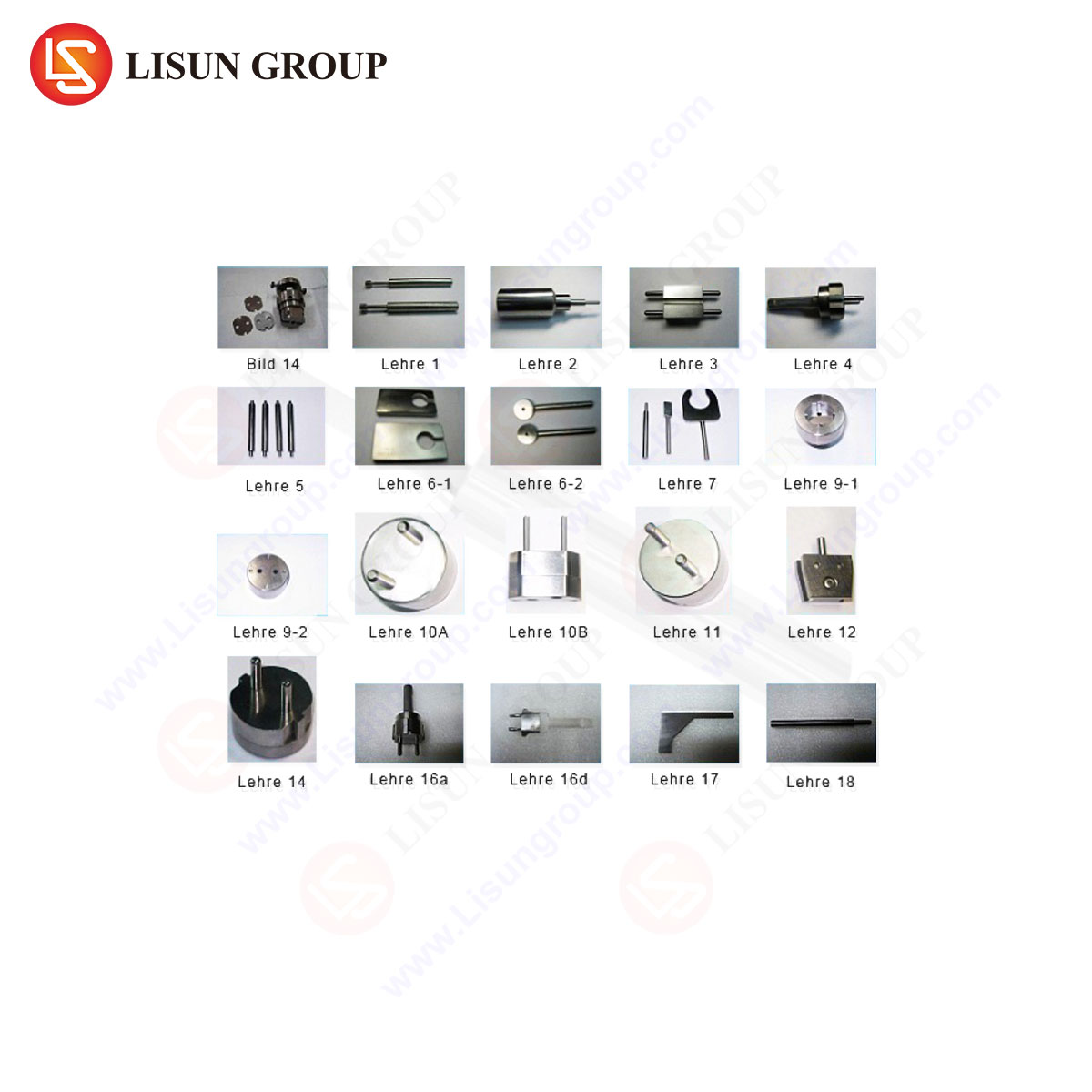
While the specific numeral “118.1” may correspond to a figure in a particular standard (e.g., certain versions of IEC 60884-1), the testing paradigm it represents is universal. Such a figure typically specifies the design and use of a suite of gauges intended to verify critical safety-related dimensions. A comprehensive test set generally includes:
- Pin Gauges: These verify the minimum and maximum dimensions of live and earth pins. A “Go” gauge, representing the maximum allowable material condition, must freely enter a specified depth. A “No-Go” gauge, representing the minimum allowable material condition, must not enter beyond a very limited initial engagement. This ensures pins are not too large (posing insertion risk) nor too small (posing contact risk).
- Socket Gauge (Plug Body Gauge): This is often the most complex gauge, designed to verify that the plug will not enter a socket-outlet in an unsafe manner. It typically checks for:
- Correct Pin Alignment: The gauge has apertures corresponding only to the correct pin configuration.
- Shutter Mechanism Operation: For sockets with protective shutters, the gauge ensures the shutters open only under the correct sequence and pressure from the earth pin (where applicable).
- Resistance to Unsafe Insertion: The gauge will have protrusions or shapes designed to block insertion if a user attempts to force a plug in with bent pins or using objects like keys or nails.
- Spacing Gauges: These verify the critical distances between pin centers. Incorrect spacing can allow a plug to make contact with the wrong terminals in a socket, creating a short circuit or incorrect polarity connection.
- Profile Gauges: These check the overall contour of the plug body to prevent the use of plugs from one national system in the socket-outlets of another, a primary safety goal.
The application of these gauges follows a strict procedure involving specified forces (e.g., 40N ± 2N for insertion) and angles. The results are quantifiable and repeatable, forming the bedrock of type-test certification.
Instrumentation for Precision: The LISUN Gauges for Plugs and Sockets System
Executing the tests dictated by standards such as Figure 118.1 requires instrumentation that transcends simple manual gauge blocks. Modern testing demands precision, data recording, and ergonomic repeatability. Systems like the LISUN Gauges for Plugs and Sockets are engineered to meet these rigorous laboratory and production line requirements.
The LISUN system is a fully integrated gauging station designed to automate and quantify the application of force and displacement during gauge testing. Its core specifications and operating principles align directly with the demands of international standards:
- Force Application and Measurement: The system incorporates a calibrated force sensor and drive mechanism capable of applying the precise normal force specified in standards (e.g., 40N) with a tolerance typically within ±1%. This eliminates the variability inherent in manual pressure application.
- Displacement Transduction: A high-resolution displacement sensor measures the exact travel distance of the gauge or plug during the test. This allows for quantitative measurement of insertion depth, not just a qualitative pass/fail. For instance, it can record that a “No-Go” pin gauge was rejected after 2.1mm of travel, providing objective data.
- Modular Gauge Fixturing: The apparatus features a rigid, reference-grade mounting platform for interchangeable gauge fixtures. Each fixture—whether for a British BS 1363 plug, an Australian AS/NZS 3112 socket, or a European Schuko CEE 7/4 system—is machined to the exact dimensional requirements of the relevant standard’s test figures.
- Programmable Test Sequences: The system’s controller can be programmed with specific test routines. For a socket-outlet test, it can first apply the earth pin gauge to open shutters, then apply the live pin gauge with defined force and measure depth, automating the multi-step process.
- Data Logging and Output: All test parameters (force, displacement, time) are logged and can be output for certification documentation or Statistical Process Control (SPC) analysis. This traceability is essential for ISO 17025 accredited laboratories and high-volume manufacturers.
Technical Specifications Table: LISUN Gauges for Plugs and Sockets (Representative Model)
| Parameter | Specification | Relevance to Standard Testing |
| :— | :— | :— |
| Force Range | 0 – 100 N | Covers all common standard requirements (e.g., 40N, 50N). |
| Force Resolution | 0.1 N | Enables precise application and measurement of mandated forces. |
| Displacement Range | 0 – 50 mm | Sufficient for full pin insertion and over-travel measurements. |
| Displacement Resolution | 0.01 mm | Provides quantitative depth data for pass/fail analysis. |
| Test Speed | 1 – 500 mm/min (programmable) | Allows for controlled, repeatable insertion rates. |
| Data Interface | USB, RS-232, Ethernet | Facilitates integration with laboratory data management systems. |
| Gauge Standards | Custom fixtures for IEC, UL, BS, AS/NZS, GB, etc. | Directly implements the geometries from standards like Figure 118.1. |
Industry Applications and Use Case Scenarios
The application of formalized gauge testing spans the entire product lifecycle of plugs and socket-outlets.
- Research, Design, and Prototyping: During the design phase, engineers use gauge systems to validate their CAD models against target standards. Iterative testing with “Go/No-Go” gauges helps refine mold designs and pin stamping tools before capital investment in production tooling is committed.
- Type Testing and Certification: For a product to receive a mark from UL, Intertek (ETL), TÜV, or other National Certification Bodies (NCBs), it must undergo rigorous type testing. A certified laboratory will use a system like the LISUN gauges to perform the exact tests prescribed in the standard, generating the objective, calibrated data required for the test report. The system’s accuracy and traceability are critical for audit compliance.
- Incoming Quality Control (IQC) for Component Manufacturers: Manufacturers of pins, plug bodies, or socket contacts perform gauge testing on incoming raw materials or sub-components. SPC data from automated tests can trigger alerts if pin diameters from a metal stamping supplier begin to drift toward the upper tolerance limit.
- Production Line Sampling and Audit: While 100% testing on a high-speed line may use simpler fixtures, automated gauging stations are deployed for periodic audit checks and failure analysis. When a plug fails a routine check, it can be brought to the gauging station for a full diagnostic test to determine which specific dimension (pin diameter, spacing, or body profile) is non-compliant, guiding corrective maintenance on the specific molding tool or assembly jig.
- Market Surveillance and Compliance Verification: Regulatory authorities and consumer safety organizations use such equipment to test products sourced from the market, ensuring ongoing compliance and identifying substandard or counterfeit goods that pose a public safety risk.
Competitive Advantages of Automated Gauging Systems
Transitioning from manual gauge sets to an automated system like the LISUN platform offers several distinct technical and operational advantages that directly address the limitations of traditional methods.
- Elimination of Operator-Induced Variance: Manual testing relies on the technician’s consistent application of force and judgment of “free movement.” Automated systems apply identical, calibrated force for every test, ensuring results are a function of the part, not the operator.
- Quantitative Data over Qualitative Judgment: Instead of a simple pass/fail, the system provides a numerical value for insertion force and depth. A plug that passes but requires 38N of force (close to the 40N limit) can be flagged for investigation, predicting potential future non-conformance.
- Enhanced Traceability and Audit Readiness: Every test is a data record including timestamp, operator ID, part ID, and all measured parameters. This creates an immutable chain of evidence for quality audits and certification renewals.
- Ergonomic and Throughput Improvements: Automated force application reduces repetitive strain for technicians. Furthermore, programmable test sequences and rapid fixture changes increase the throughput of a certification laboratory or QC lab, allowing more samples to be tested to a higher standard of evidence.
- Diagnostic Capability: When a failure occurs, the system’s data pinpoints the nature of the failure—excessive insertion force, incorrect depth, etc.—accelerating root cause analysis and corrective action in the manufacturing process.
Integration with Broader Compliance Testing Regimes
It is crucial to position dimensional gauge testing within the holistic compliance testing ecosystem. While foundational, it is one node in a network of evaluations. A plug that passes gauge tests must subsequently be validated for:
- Electrical Performance: Contact resistance, dielectric strength, and earthing continuity tests.
- Mechanical Endurance: Insertion/withdrawal cycle tests, cord anchorage strain relief tests, and impact tests.
- Thermal and Environmental Performance: Temperature rise tests under load, heat resistance, and aging tests.
The data from initial gauge testing often informs the setup and expectation for these subsequent tests. A plug at the upper limit of pin size may exhibit higher insertion force and different wear characteristics during endurance testing. Therefore, the gauging system provides the initial, critical dataset that contextualizes all further safety evaluations.
Conclusion
The testing principles embodied in standards such as Figure 118.1 represent a distilled engineering response to fundamental electrical safety hazards. The move from manual gauge interpretation to automated, data-centric systems marks a significant evolution in quality assurance for the electrical accessory industry. Implementations like the LISUN Gauges for Plugs and Sockets system exemplify this evolution, transforming a binary check into a rich source of quantitative process data. By ensuring absolute dimensional compliance with an unprecedented level of objectivity and traceability, such technology underpins not only product certification but also the continuous improvement of manufacturing processes, ultimately contributing to the enhanced safety and reliability of the global electrical infrastructure.
FAQ Section
Q1: Can a single LISUN gauging system test multiple international plug standards?
Yes, the system is designed with a modular fixture platform. The core force and measurement unit remains constant. Testing different plug types (e.g., UK, EU, US, AU) requires changing the specific, machined gauge fixture that mounts onto the platform. These fixtures are manufactured to the exact dimensional specifications of each standard’s test figures.
Q2: How does automated gauging handle the testing of socket-outlet shutter mechanisms?
The system can be programmed for multi-stage test sequences. A common routine involves first using an “earth pin only” gauge fixture, applying the specified force to verify the shutters open correctly. Subsequently, a “live pin gauge” fixture is used to verify that the shutters, now opened by the earth pin simulation, allow correct insertion of the phase and neutral pins while blocking incorrect insertion attempts. The system measures the force and travel at each stage.
Q3: What is the typical calibration interval for such a system, and what standards govern its accuracy?
The recommended calibration interval is annually, aligned with standard laboratory practice for force and displacement transducers. The system’s own accuracy is traceable to national metrology institutes (e.g., NIST). Its design and validation should conform to relevant standards for test equipment, such as ISO/IEC 17025 requirements for testing laboratories, ensuring its measurements are fit for purpose in a certification environment.
Q4: Beyond pass/fail, how can the quantitative data from this system be used proactively?
The data is invaluable for Statistical Process Control (SPC). By tracking metrics like mean insertion force and dimensional variation over time, manufacturers can identify trends. A gradual increase in pin diameter, still within spec, can signal tool wear in a stamping machine, allowing for predictive maintenance before non-conforming parts are produced. This shifts quality control from a detection-based to a prevention-based model.
Q5: Is the system suitable for testing miniaturized or specialized connectors (e.g., IEC 60320 appliance inlets)?
While primarily designed for standard mains plugs and sockets, the principle is applicable. The system’s capability depends on the available force range and resolution, as well as the ability to manufacture precise, miniature gauge fixtures. For specialized connectors, consultation with the manufacturer is required to confirm the feasibility of creating custom fixtures that match the relevant connector standard’s gauge specifications.