


A Technical Examination of Plug and Socket Gauge Systems Under NF C 61-314
The verification of dimensional conformity for plugs and socket-outlets represents a foundational activity within the electrical components industry, serving as a critical barrier against non-compliant products entering the market. This process, governed by stringent national and international standards, ensures interoperability, user safety, and long-term reliability of electrical connections. Central to this verification regime is the use of standardized gauges, precision instruments designed to provide unambiguous, repeatable assessments of mechanical dimensions. This article provides a detailed analysis of the principles and applications outlined in Figure C1 of the French standard NF C 61-314, a seminal document specifying the gauge requirements for plugs and socket-outlets. Furthermore, it examines the implementation of these principles in modern testing apparatus, with a specific focus on the LISUN Gauges for Plugs and Sockets.
The Foundational Role of NF C 61-314 in Dimensional Compliance
NF C 61-314, and its harmonized European counterpart, establishes the mandatory mechanical, electrical, and thermal requirements for plugs, socket-outlets, and associated apparatus. Its authority stems from its precise definition of tolerances and geometries that ensure compatibility across manufacturers and prevent hazardous conditions such as inadequate contact pressure, partial insertion, or access to live parts. Within this framework, Figure C1 is not merely an illustration but a normative data set that codifies the exact dimensions and functional application of a series of gauges. These gauges are categorized primarily into “GO” and “NO-GO” types, a metrological concept borrowed from industrial quality control. The “GO” gauge must fit within or upon the device under test under a specified force, confirming that minimum required dimensions are met. Conversely, the “NO-GO” gauge must not fit, or fit only to a very limited extent, verifying that maximum dimensional limits are not exceeded. This binary assessment provides a rapid and definitive verdict on a sample’s conformance to the standard’s critical safety dimensions.
Deconstructing the Gauge Classifications in Figure C1
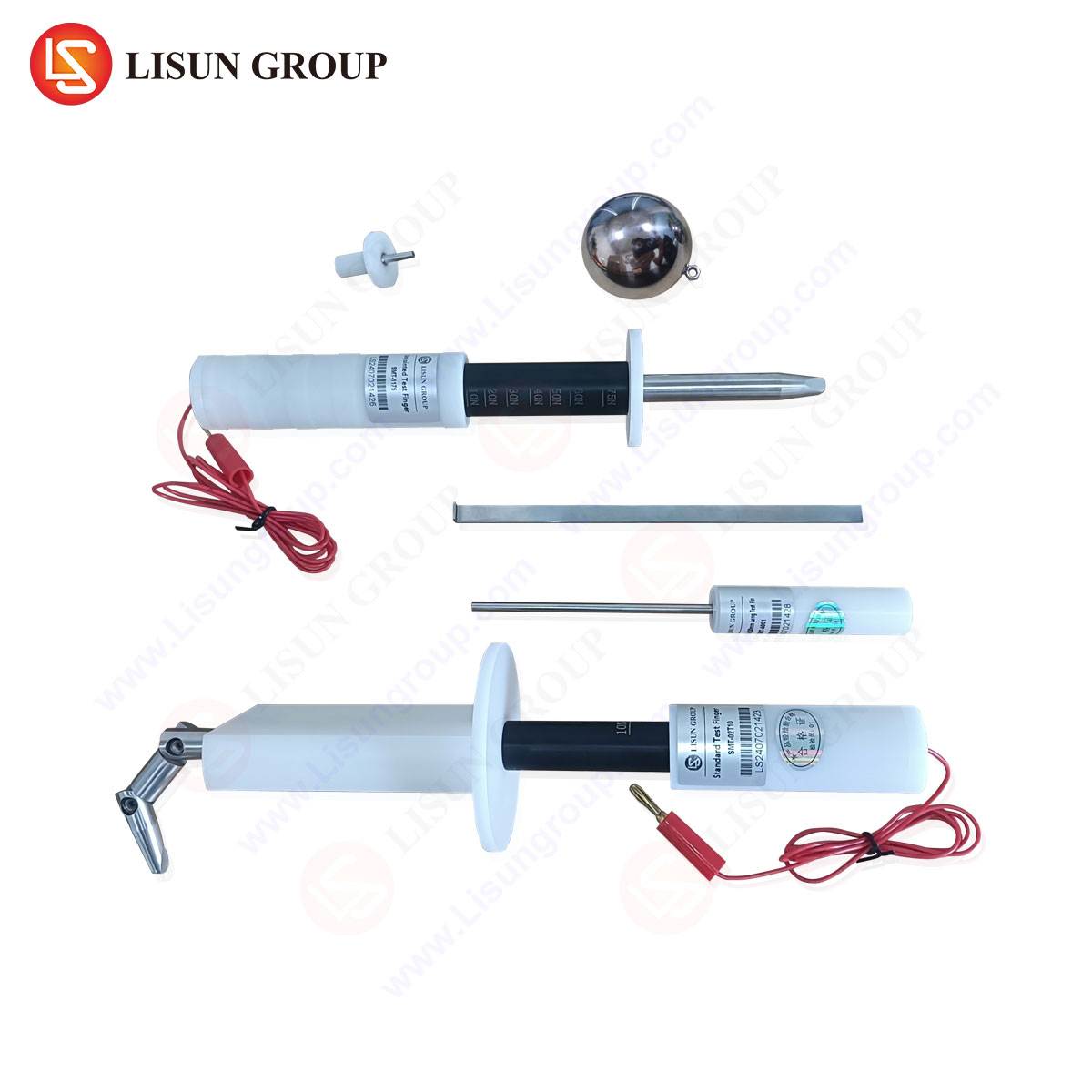
Figure C1 of NF C 61-314 delineates several distinct gauge types, each engineered to verify a specific geometric feature of a plug or socket-outlet. A thorough understanding of each gauge’s purpose is essential for accurate interpretation of test results.
The Pin Gauge is applied to socket-outlets to verify that the entry apertures for the plug’s pins are not too small, which would prevent insertion, nor too large, which could lead to poor contact alignment or user access to live parts. The “GO” side of the pin gauge, representing the minimum aperture size, must enter the contact orifice freely. The “NO-GO” side, representing the maximum permissible aperture, must not fully enter. This test directly assesses the risk of electric shock and the functional integrity of the mating connection.
The Check Gauge serves a complementary role, typically used to verify the internal configuration of a socket-outlet, ensuring that shutters or protective barriers function correctly and that the spacing between contacts is adequate to prevent flashover. Its design is often more complex, simulating the profile of a standard plug to interact with the socket’s internal safety mechanisms.
The Section Gauge and Profile Gauge are critical for plug assessment. The section gauge examines the cross-sectional dimensions of the plug’s pins, ensuring they are not undersized (which could cause overheating due to insufficient current-carrying capacity) or oversized (which could damage the socket-outlet’s contacts upon insertion). The profile gauge assesses the overall external contour of the plug, verifying that it does not exceed the maximum dimensions, which is vital for ensuring the plug can be inserted into a standardized mounting box or enclosure without force.
Operational Mechanics and Force Application in Gauge Testing
The application of gauges is not a simple manual exercise; it is a procedure governed by precise forces and conditions to ensure repeatability. NF C 61-314 specifies the exact forces to be applied during gauge tests. For instance, a “GO” pin gauge must be inserted into a socket-outlet with a defined force, often measured in Newtons (N), to simulate the action of a user plugging in a device. If the gauge does not enter under this force, the socket is deemed non-compliant. Similarly, the “NO-GO” gauge is applied with a minimal force; any significant entry constitutes a failure. The LISUN gauge systems incorporate calibrated mechanical or electromechanical actuators to apply these forces with high precision, eliminating the variability inherent in manual testing. This automation ensures that test results are objective, auditable, and consistent across different operators and laboratories, a necessity for certification bodies like UL, VDE, and Intertek.
The LISUN Implementation of Standardized Gauge Testing
The LISUN Gauges for Plugs and Sockets represent a modern, engineered solution that translates the normative requirements of standards like NF C 61-314 into a reliable, efficient, and comprehensive testing workflow. These systems are not simple replicas of the gauges in Figure C1 but are integrated into test apparatus that provides the necessary control and measurement capabilities.
Specifications and Construction: LISUN gauges are manufactured from hardened, dimensionally stable tool steel or other durable materials with negligible thermal expansion coefficients. This ensures that the critical dimensions specified in Figure C1 remain invariant across a range of environmental conditions. The surface finish is precisely controlled to a specified roughness to prevent binding or false failures due to friction, rather than dimensional non-conformity. Each gauge set is certified with a calibration report traceable to national metrology institutes, providing the documentation required for accredited laboratory testing.
Testing Principles and Automation: A key advantage of the LISUN system is its integration of force measurement and displacement sensing. When a “GO” gauge is actuated, the system not only applies the standard-mandated force but also monitors the travel distance. A pass/fail decision is made automatically based on whether the gauge achieves full travel under the correct force. For “NO-GO” tests, the system detects any displacement beyond a permissible threshold. This data is often logged by accompanying software, generating a test report that includes applied force, displacement over time, and a final verdict. This level of data integrity is crucial for failure analysis and quality trend monitoring.
Industry Use Cases and Application: The primary application of LISUN gauges is in the quality control laboratories of plug and socket manufacturers. Here, they are used for incoming raw material inspection, in-process checks during molding and assembly, and final product audit. Furthermore, they are indispensable tools for independent testing laboratories that provide product certification. A specific use case involves testing the safety shutters in socket-outlets. A specialized LISUN check gauge, designed to the geometry in NF C 61-314, is used to verify that the shutters open correctly for a plug’s live and neutral pins but resist opening when a single object (like a child’s finger or a probe) is inserted into the earth contact opening. This test directly validates a critical safety feature.
Comparative Advantages in Manufacturing and Certification
The transition from manually operated, standalone gauges to an integrated system like LISUN’s offers several distinct competitive advantages that impact both manufacturing efficiency and regulatory compliance.
The first is Enhanced Repeatability and Reduced Operator Influence. Manual gauge application is susceptible to variations in the angle and velocity of insertion, leading to inconsistent results. The mechanized application in LISUN systems standardizes the test procedure, ensuring that a product tested in Europe yields the same result as an identical product tested in Asia, provided the same standard is referenced.
The second advantage is Data Traceability and Documentation. In modern quality management systems, simply recording a “pass” or “fail” is insufficient. Regulators and corporate customers demand objective data. LISUN systems provide digitized records of the entire test cycle—force vs. displacement curves—which serve as immutable evidence of compliance and are invaluable for diagnosing the root cause of a failure, such as a slightly misaligned contact spring or a molding flash obstructing a pin aperture.
The third is Testing Throughput and Labor Efficiency. An automated gauge station can perform a series of checks—pin gauge, profile gauge, check gauge—in a fraction of the time required for a manual operator, and without fatigue. This allows for 100% inspection on high-volume production lines, a practice that was previously economically unfeasible, thereby significantly reducing the risk of batch-level non-conformities.
Interoperability with Global Standards and Future-Proofing
While NF C 61-314 is a specific standard, the underlying principle of gauge-based verification is universal. The design of LISUN gauge systems is modular, allowing for the quick interchange of gauge heads to accommodate different national standards such as BS 1363 (UK), AS/NZS 3112 (Australia/New Zealand), and NEMA configurations (North America). This flexibility is critical for manufacturers producing for a global market, as it consolidates multiple testing requirements into a single, programmable platform. Furthermore, as standards evolve—for instance, to accommodate new materials or safety requirements—the system’s software and mechanical interfaces can be updated, protecting the capital investment and ensuring long-term relevance in a dynamic regulatory landscape.
Frequently Asked Questions (FAQ)
Q1: How often do LISUN gauges require calibration, and what is the process?
A1: The calibration interval for LISUN gauges is typically recommended annually, though this can be adjusted based on usage frequency and the requirements of the laboratory’s accreditation body (e.g., ISO/IEC 17025). The calibration process involves a certified metrology lab using coordinate measuring machines (CMM) to verify that every critical dimension on the gauge remains within the tolerances specified by the applicable standard, such as NF C 61-314. A new certificate of calibration is issued upon successful verification.
Q2: Can the LISUN system test for the mechanical strength of shutters in socket-outlets, beyond just dimensional checks?
A2: Yes, advanced LISUN configurations can be equipped with dynamic force sensors and actuators programmed to perform endurance and strength tests. For example, the system can be set to cycle a check gauge in and out of a socket-outlet thousands of times to test shutter durability, or to apply an increasing force to a shutter to measure the point of failure, ensuring it meets the standard’s mechanical strength clauses.
Q3: Our company manufactures plugs for the British (BS 1363) and German (Schuko) markets. Can one LISUN system handle both?
A3: Absolutely. The LISUN system is designed with a modular architecture. Different gauge sets and often different fixture plates are used for each plug and socket type. The system’s software contains pre-loaded test profiles for a wide range of international standards. An operator simply selects the relevant standard (e.g., BS 1363 or NF C 61-314), the system prompts for the correct gauge to be installed, and it automatically applies the correct forces and pass/fail criteria.
Q4: What happens if a “NO-GO” gauge partially enters a socket-outlet? Is this an immediate failure?
A4: The standards are very precise on this point. NF C 61-314 typically specifies that a “NO-GO” gauge must not enter an aperture, or in some cases, must not enter beyond a very minimal, specified depth (e.g., 1 mm). Any entry beyond this defined limit constitutes a failure. The LISUN system is programmed with this exact threshold, and its sensitive displacement sensors will trigger a failure if the gauge travel exceeds the permitted value, ensuring strict adherence to the standard.