


Understanding Glow Wire Testing for Electrical Components: A Critical Evaluation of Fire Hazard Assessment
Introduction to Fire Hazard Evaluation in Electrotechnical Products
The proliferation of electrical and electronic equipment across domestic, commercial, and industrial environments has necessitated the development of rigorous safety standards to mitigate fire risks. One predominant ignition source in such equipment stems from overheated components or faulty connections that can reach sufficiently high temperatures to ignite adjacent materials. Traditional flammability tests often fail to replicate this specific thermal stress condition. Consequently, glow wire testing has emerged as a fundamental compliance assessment, simulating the effect of thermal energy from an electrically heated element on a product’s non-metallic parts. This methodology provides a quantifiable measure of a material or assembly’s resistance to ignition, flame propagation, and dripping of burning particles. The test’s relevance spans a vast array of sectors, including household appliances, automotive electronics, lighting fixtures, and medical devices, forming a cornerstone of product safety certification globally.
Fundamental Principles of the Glow Wire Test Methodology
The core principle of glow wire testing involves the application of a specified temperature to a test specimen using a electrically heated, standardized wire loop—the glow wire. This element, typically composed of a nickel/chromium alloy with a diameter of 4.0 mm, is heated by the passage of an electric current to a precise temperature, calibrated between 550°C and 960°C depending on the applicable severity. The test apparatus forces the glowing wire, maintained at the target temperature, against the test specimen with a defined force of 1.0 N ± 0.2 N for a period of 30 seconds ± 1 second.
The evaluation criteria are multifaceted and observed during and after the application period. Key parameters include:
- Ignition Time (ti): The duration from initial contact until sustained flaming combustion of the specimen occurs.
- Flame Extinguishment Time (te): The time elapsed from the removal of the glow wire until any generated flames self-extinguish.
- Presence of Flaming or Glowing Particles: Observation of whether burning or glowing debris detaches from the specimen, potentially igniting a tissue paper substrate placed below.
- Specimen Deformation: Assessment of the physical damage, including penetration depth or hole formation.
The test outcome determines a Glow Wire Flammability Index (GWFI) or a Glow Wire Ignition Temperature (GWIT), as defined in the IEC 60695-2 series of standards. The GWFI is the highest temperature at which a material does not ignite or, if it does, extinguishes within 30 seconds after removal of the glow wire without dripping flaming particles. The GWIT is the temperature 25°C or 50°C (depending on the temperature grade) above the maximum test temperature at which the material does not ignite for a duration of more than 5 seconds.
Standards Framework and Regulatory Compliance Imperatives
Glow wire testing is codified within an extensive international standards framework, primarily under the auspices of the International Electrotechnical Commission (IEC). The pivotal standard is IEC 60695-2-10:2013, “Glowing/hot-wire based test methods – Part 2-10: Glow-wire apparatus and common test procedure,” which details the apparatus requirements and fundamental test method. This is supplemented by:
- IEC 60695-2-11: Guidance for testing pre-selected materials for GWFI determination.
- IEC 60695-2-12: Guidance for testing pre-selected materials for GWIT determination.
- IEC 60695-2-13: Details the specific test procedure for products.
These foundational standards are adopted and referenced by numerous sector-specific and regional regulations. For instance, the IEC 60335 series for household appliances, IEC 60598 for lighting fixtures, and IEC 60950 for information technology equipment (now superseded but historically relevant) all incorporate glow wire requirements. In the automotive sector, similar principles are embedded within various ISO and SAE specifications. Compliance with these standards is not merely a technical formality but a legal prerequisite for market access in most global jurisdictions, underpinning certifications such as the CE Mark in Europe, UL listing in North America, and CCC in China.
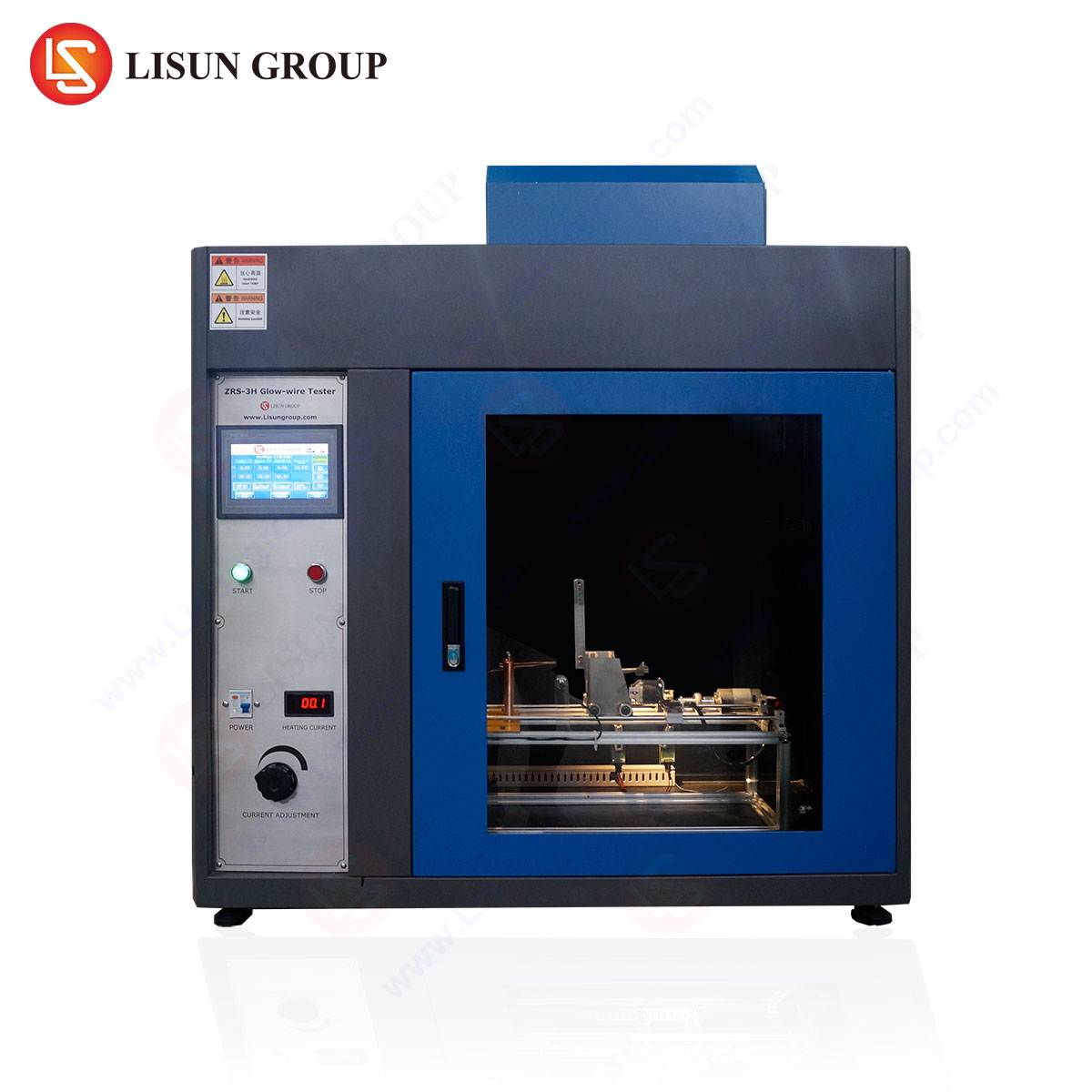
Apparatus Specification: The LISUN ZRS-3H Glow-wire Test Apparatus
Accurate and reproducible test results are wholly dependent on the precision, reliability, and compliance of the testing apparatus. The LISUN ZRS-3H Glow-wire Test Apparatus represents a fully integrated system engineered to meet the exacting specifications of IEC 60695-2-10, GB/T5169.10-13, and other equivalent national standards. Its design prioritizes operational fidelity, user safety, and data integrity.
Key Technical Specifications and Features:
- Temperature Control System: Utilizes a high-precision PLC (Programmable Logic Controller) in conjunction with a PID (Proportional-Integral-Derivative) algorithm for closed-loop temperature regulation. The system achieves a control range from 500°C to 1000°C with a stability of ± 2°C at the calibration point, ensuring the glow wire maintains the target temperature within the strict tolerances mandated by the standard.
- Glow Wire Fixture: The apparatus incorporates a meticulously machined glow wire holder that ensures consistent orientation and secure mounting of the standard Ni/Cr wire loop. The applied force mechanism is calibrated to deliver the required 1.0 N ± 0.2 N contact pressure via a calibrated weight and lever system, eliminating variability from manual pressure application.
- Specimen Mounting and Positioning: A fully adjustable test stand allows for precise three-dimensional positioning of the test specimen relative to the glow wire. This is critical for ensuring the correct contact point and angle, as specified for end-product testing (e.g., for switches or enclosures).
- Timing and Measurement Integration: Digital timers automatically record the ignition time (ti) and flame extinguishment time (te) with millisecond resolution. Sensors can be integrated to detect flame presence objectively, reducing observer-dependent error.
- Safety Enclosure: A transparent, interlocked safety chamber constructed from reinforced materials contains the test. The interlock system immediately cuts power to the glow wire if the chamber door is opened during a test, protecting the operator from high temperatures and potential flare-ups.
- Calibration and Validation: The design facilitates straightforward calibration using standard thermocouples and reference materials. Features such as a dedicated calibration port and software-assisted validation routines simplify the periodic verification required to maintain laboratory accreditation (e.g., ISO/IEC 17025).
Industry-Specific Applications and Test Scenarios
The application of glow wire testing is dictated by the potential fire hazard presented by a product’s design and intended use environment.
- Household Appliances & Consumer Electronics: Components such as switch housings, connector bodies, internal supports, and insulation bobbins within food processors, washing machines, or televisions are tested. For example, a socket outlet’s surrounding plastic faceplate would be subjected to testing at 850°C or 960°C to ensure a faulty, overheated plug does not ignite it.
- Automotive Electronics: With the increasing electrification of vehicles, components like battery management system housings, charging port assemblies, and wiring harness connectors are evaluated. The confined, oxygen-rich, and vibration-prone environment of a vehicle makes resistance to ignition from short-circuit events paramount.
- Lighting Fixtures: Plastic diffusers, lamp holders, and body housings for LED luminaires, especially those operating at high temperatures or in enclosed spaces, are common test subjects. The test verifies that a failure in the driver or LED module will not cause the fixture to become a fire source.
- Industrial Control Systems & Telecommunications Equipment: Enclosures for PLCs, terminal blocks, server racks, and router housings are tested to prevent fire propagation within control rooms or data centers, where collateral damage from a single component failure could be catastrophic.
- Medical Devices & Aerospace Components: For devices like patient monitors or in-flight entertainment systems, the test assesses non-metallic materials used in casings and internal structures. The stringent safety cultures in these fields often demand testing at higher severity levels or as part of a broader failure mode and effects analysis (FMEA).
- Electrical Components and Wiring Systems: This is the test’s origin domain. Switches, circuit breaker casings, cable ties, and insulation sleeves are directly evaluated to ensure they do not propagate fire from an internal overload or fault condition.
Interpreting Test Results and Material Selection Implications
The data derived from glow wire testing transcends simple pass/fail metrics. The recorded ti and te values provide engineers with comparative data for material selection. A longer ignition time indicates a higher inherent resistance to ignition from a localized heat source. A short flame extinguishment time is desirable, demonstrating that the material does not support sustained combustion once the ignition source is removed.
Material formulators use GWFI and GWIT ratings as key performance indicators. Engineering plastics like polycarbonate (PC), polyamide (PA, e.g., Nylon), and acrylonitrile butadiene styrene (ABS) are often compounded with flame-retardant additives—such as halogenated compounds, phosphorus-based agents, or mineral fillers like aluminum trihydroxide—to achieve the required ratings for a given application (e.g., 750°C GWFI for a printer housing or 850°C GWIT for a power supply enclosure). The test thus drives innovation in material science, pushing for formulations that balance flammability resistance with other critical properties like mechanical strength, dielectric performance, and cost.
Operational Advantages of Automated Test Systems
Modern apparatuses like the LISUN ZRS-3H confer significant advantages over rudimentary or semi-automated setups. Automation of temperature ramping, dwell time, application force, and timing measurements eliminates numerous sources of human error, enhancing repeatability and reproducibility (key tenets of ISO/IEC 17025). The integrated data logging capabilities allow for the seamless generation of test reports, including temperature profiles, timing data, and observer notes, which is essential for audit trails and certification submissions.
Furthermore, the enhanced safety features—interlocked chambers, fume extraction ports, and emergency cut-offs—protect laboratory personnel and equipment. The robustness and calibration stability of such systems reduce downtime and maintenance costs, ensuring consistent throughput for quality control or third-party testing laboratories. In a competitive manufacturing landscape, the reliability of compliance testing equipment directly impacts time-to-market and reduces the risk of costly non-conformities.
Future Trajectories in Fire Safety Testing
The evolution of glow wire testing continues in parallel with technological advancement. Standards bodies are perpetually reviewing test methods to address new materials, such as high-performance polymers and biocomposites, and novel product forms. There is a growing emphasis on testing complete assemblies and sub-assemblies rather than just raw material plaques, as the interaction between different materials (e.g., plastic, metal, adhesive) can significantly alter fire behavior.
The integration of advanced diagnostics, such as high-speed infrared thermography to map heat spread or mass loss calorimetry coupled with glow wire initiation, is an area of research, providing deeper insights into ignition and flame spread dynamics. Additionally, the drive towards halogen-free and environmentally sustainable flame retardants will keep glow wire testing at the forefront of material validation, ensuring that new “green” materials do not compromise fundamental fire safety.
Frequently Asked Questions (FAQ)
Q1: What is the primary difference between GWFI and GWIT, and how do I specify which is required?
GWFI (Glow Wire Flammability Index) is a “pass/fail” test at specific temperature increments to find the highest temperature at which the material does not create a fire hazard. GWIT (Glow Wire Ignition Temperature) is a more stringent test to determine the temperature at which the material does not ignite at all. The required parameter is dictated by the end-product standard (e.g., IEC 60335-1 for appliances). GWIT is generally considered a more conservative and increasingly specified requirement.
Q2: Can the LISUN ZRS-3H apparatus be used for testing both finished products and material samples?
Yes. The apparatus is designed with a fully adjustable test stand and specimen holder that can accommodate a wide range of specimen geometries. It can be configured for the standardized rectangular test plaques used for material qualification (per IEC 60695-2-11/12) as well as for the product-specific test configurations mandated by IEC 60695-2-13, where the glow wire is applied to a specific location on an actual switch, enclosure, or other component.
Q3: How often does the glow wire element itself need to be replaced, and what affects its lifespan?
The nickel/chromium glow wire is a consumable item. Its lifespan depends on the test temperatures used; frequent testing at the upper range (e.g., 960°C) will accelerate oxidation and embrittlement. Regular visual inspection for significant pitting, distortion, or diameter reduction is necessary. Replacement is required when the wire no longer meets the dimensional specifications of the standard or shows signs of failure. Proper calibration before each test session will also indicate when wire degradation is affecting temperature stability.
Q4: Our product contains multiple plastic types. Do we need to test every single material?
The testing strategy should be based on a hazard analysis. Typically, materials that are within a certain distance (often 3mm) of current-carrying parts that could overheat, or that form the external enclosure, are considered for testing. However, many standards allow for testing the “most critical” part—the material deemed most likely to ignite based on thickness, composition, and location. A conservative approach and consultation with the relevant product standard and certification body are recommended.
Q5: Is glow wire testing sufficient for complete fire hazard assessment of our electronic product?
No, glow wire testing is a specific hazard-based test simulating one ignition source. A comprehensive fire hazard assessment typically involves a suite of tests. This may include needle-flame tests (for small flames), horizontal/vertical flame tests (UL 94), tracking resistance tests (high-voltage arcing), and overload tests on actual circuits. Glow wire is a critical component of this suite but is part of a broader “fire safety engineering” approach mandated by product safety standards.