


Understanding Glow Wire Testing for Product Compliance and Safety
The proliferation of electrical and electronic equipment across domestic, commercial, and industrial environments has necessitated the development of rigorous safety standards to mitigate fire hazard risks. Among the suite of tests employed to evaluate a product’s resistance to ignition and flame propagation, the Glow-Wire Test stands as a critical, simulation-based assessment. This procedure evaluates the ability of insulating materials and other non-metallic parts to withstand thermal stresses caused by overheated or glowing components within an appliance, without initiating a fire. The test’s principle is not to replicate a direct flame but to simulate a severe fault condition—such as an overloaded resistor, a poor connection, or an overheated element—pressing against adjacent materials. Compliance with glow-wire testing standards, primarily the IEC 60695-2 series, is a mandatory prerequisite for product certification in global markets, governing sectors from household appliances to aerospace components.
The Thermodynamic Principles of Glow-Wire Ignition Testing
At its core, the glow-wire test is an investigation into a material’s response to a localized, persistent thermal insult. The test employs a standardized heating element, typically a coiled wire of nickel/chromium (80/20) alloy with a specified shape, which is electrically heated to a precise temperature. This temperature, ranging from 550°C to 960°C depending on the applicable test severity, is maintained within a tight tolerance (± 10°C) prior to application. The thermodynamic interaction involves three primary modes of heat transfer: conduction from the wire to the specimen surface, convection to the surrounding atmosphere, and radiation from the incandescent element.
The test outcome hinges on the material’s thermal properties, including its ignition temperature, thermal conductivity, heat capacity, and propensity for forming insulating char. A material with high thermal conductivity may dissipate heat rapidly, preventing localized temperature rise above the ignition point. Conversely, a material with low conductivity may experience intense local heating, leading to pyrolysis—the thermal decomposition of organic constituents—and the subsequent release of flammable volatiles. If the concentration and temperature of these volatiles at the material-air interface reach critical levels, piloted ignition occurs, sustained by the glow-wire itself acting as a permanent ignition source. The test measures not only ignition but also the duration and nature of any subsequent flaming, as well as the propagation of flame to surrounding materials or the production of burning droplets that could pose a secondary hazard.
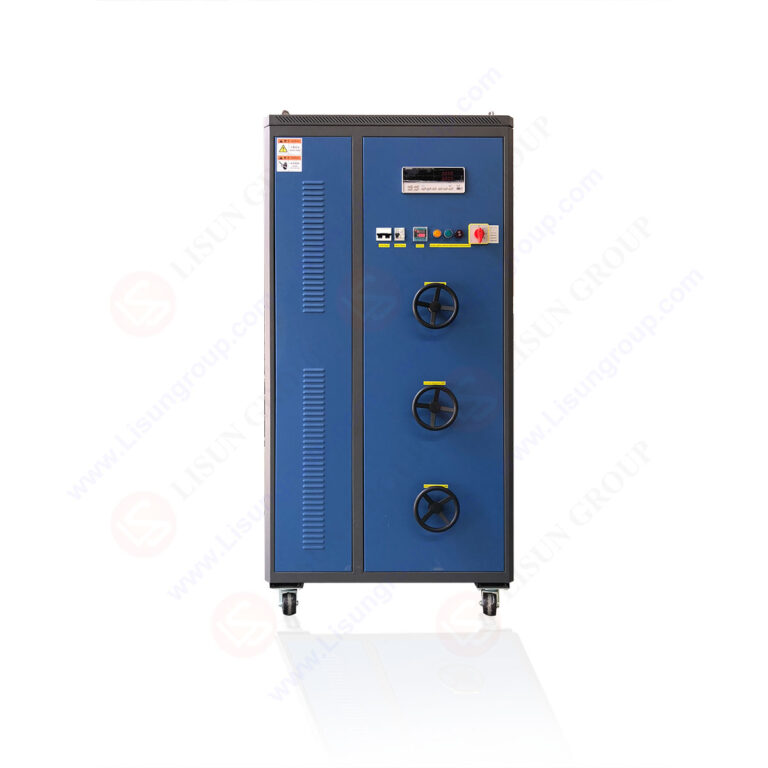
Apparatus Specification and Calibration: The LISUN ZRS-3H System
Accurate and reproducible test results are fundamentally dependent on the precision and reliability of the test apparatus. The LISUN ZRS-3H Glow-wire Test Apparatus represents a fully integrated system engineered to meet the exacting requirements of IEC 60695-2-10, IEC 60695-2-11, IEC 60695-2-12, IEC 60695-2-13, and related standards (e.g., GB/T 5169.10-13, UL 746A). Its design prioritizes operational fidelity, user safety, and calibration integrity.
The system’s central component is the glow-wire assembly, featuring a Ø4.0mm nickel-chromium wire formed into a specific loop shape. This wire is heated by a low-voltage, high-current power supply with closed-loop PID temperature control, ensuring the set temperature is achieved and maintained with minimal fluctuation. The LISUN ZRS-3H incorporates a high-precision K-type thermocouple, spot-welded to the underside of the glow-wire loop, providing direct and immediate temperature feedback to the digital controller. A key specification is its temperature range, typically spanning 500°C to 1000°C, covering all standard test severities (e.g., 550°C, 650°C, 750°C, 850°C, 960°C).
The apparatus includes a mechanized application system that applies the heated glow-wire to the test specimen with a defined force of 1.0 N ± 0.2 N. This is achieved via a calibrated weight and lever system, guaranteeing consistent contact pressure—a variable critically influential on heat transfer rates. The specimen holder is adjustable to accommodate products and sub-assemblies of varying geometries. Below the test position, a specified layer of tissue paper (typically weighing between 12 g/m² and 30 g/m²) is mounted on a wooden base to assess the hazard posed by ignited droplets or particles.
Calibration of the system is not a mere recommendation but a strict requirement for valid testing. The LISUN ZRS-3H facilitates this through its built-in calibration routines, which verify the relationship between the controller setpoint and the actual temperature measured at the thermocouple junction. Regular calibration using standardized reference materials, such as silver foil, confirms the apparatus’s performance aligns with the intrinsic temperature verification method prescribed by the standards, ensuring global inter-laboratory result comparability.
Interpreting Test Criteria and Failure Modes Across Industries
A “pass” or “fail” determination in glow-wire testing is not solely binary but is assessed against a multi-faceted set of observational criteria during and after the 30-second application period. Compliance is generally achieved if:
- No ignition of the specimen occurs, or
- Flames or glowing of the specimen extinguish within 30 seconds after removal of the glow-wire, and
- No ignition of the tissue paper below occurs from falling droplets or particles.
Failure modes are carefully categorized. Ignition and sustained flaming beyond the permitted timeframe constitutes a clear failure, indicating the material can support combustion once the fault condition initiates a fire. The production of burning or glowing droplets that ignite the tissue paper is a critical failure mode, as it signifies the potential for fire propagation to lower-lying components or surfaces—a paramount concern in vertically stacked equipment like server racks or automotive electronic control units (ECUs). Excessive deformation that would impair the safety function of a part (e.g., a connector housing that deforms to expose live parts) may also be deemed non-compliant, even in the absence of flame.
The application of these criteria varies by industry, guided by end-product standards. For Household Appliances (IEC 60335 series), a toaster’s crumb tray or a washing machine’s programmer housing may be tested at 750°C or 850°C to simulate a fault in an internal heating element or motor controller. In Automotive Electronics, connectors and sensor housings within the engine compartment are subjected to tests, often at 850°C or 960°C, reflecting the high ambient temperatures and potential for electrical faults in this harsh environment. Lighting Fixtures, particularly those housing compact fluorescent lamps or LED drivers, test plastic diffusers and terminal covers to ensure a failing ballast or driver does not ignite the fixture. For Medical Devices (IEC 60601-1), enclosures and cable management systems are evaluated to prevent fire initiation that could have catastrophic consequences in oxygen-rich or patient-critical environments.
Strategic Material Selection and Product Design Validation
Glow-wire testing is not merely a final compliance checkpoint but an integral tool in the product development and material selection process. Design engineers utilize test data to make informed decisions about polymers, composites, and other insulating materials. Materials are often classified by their Glow-Wire Flammability Index (GWFI) and Glow-Wire Ignition Temperature (GWIT).
- GWFI is the highest temperature at which a material does not ignite for more than 30 seconds after glow-wire removal and does not produce burning droplets that ignite the tissue.
- GWIT is the temperature 25°C above the maximum test temperature at which the material does not ignite for more than 5 seconds during glow-wire application.
A material with a GWFI of 850°C and a GWIT of 825°C would be suitable for applications requiring resistance to high thermal stress. By specifying materials that meet or exceed the required indices for a given component’s anticipated thermal environment and fault scenario, engineers can design in safety from the outset. The LISUN ZRS-3H apparatus is frequently employed in such R&D and quality assurance laboratories to batch-test material samples, validate supplier claims, and troubleshoot production inconsistencies before full-scale product certification tests.
Case Studies: Glow-Wire Testing in Applied Product Safety
Electrical Components: A manufacturer of miniature circuit breakers (MCBs) must test the thermoplastic housing. Using the LISUN ZRS-3H at 960°C, the test simulates a catastrophic internal fault causing extreme overheating. The housing must not ignite or develop a hole that compromises electrical insulation or allows ejection of molten material.
Telecommunications Equipment: A plastic fan grill on a network switch is tested at 750°C. A stalled fan motor could cause the windings to overheat and glow. The grill material must prevent flame from escaping the enclosure and must not drip ignited particles onto the circuit boards below, which is verified by the tissue paper indicator in the test setup.
Office Equipment: The external casing of a desktop power supply unit (PSU) is subjected to a 850°C test. This evaluates the scenario of a short-circuited transformer or rectifier. Compliance ensures that a fault contained within the PSU does not breach the enclosure and ignite nearby paper or other combustibles in an office setting.
Navigating the Regulatory Landscape and Standardization Framework
Glow-wire testing is embedded within a complex hierarchy of international, regional, and industry-specific standards. The foundational documents are the IEC 60695-2-10, -11, -12, and -13, which detail the apparatus, calibration, test procedures, and guidance for test development, respectively. These are horizontally adopted by many other product-specific vertical standards.
- IEC/EN 60335 (Household Appliances)
- IEC/EN 60950 / IEC/EN 62368 (IT & Audio-Video Equipment)
- IEC/EN 60601 (Medical Electrical Equipment)
- ISO 20653 (Automotive Degrees of Protection)
- UL 746A (Polymeric Materials – Short Term Property Evaluations)
A critical task for manufacturers and testing laboratories is to correctly identify the applicable standard, the specific components requiring testing, and the appropriate test severity (temperature) based on the product’s intended use, fault analysis, and field experience. The precision and traceability offered by apparatus like the LISUN ZRS-3H are essential for generating test reports that are accepted by certification bodies such as UL, TÜV, Intertek, and CSA, facilitating market access in North America, Europe, and Asia.
Advanced Applications and Future Trajectories in Fire Hazard Assessment
While the core methodology remains stable, the application of glow-wire testing continues to evolve. In Aerospace and Aviation, testing of materials used in cabin interiors and avionics bays is critical, with adaptations for specific airworthiness standards (e.g., FAA regulations). For Industrial Control Systems, the focus is on programmable logic controller (PLC) housings and terminal blocks in control panels, where a fault could disrupt critical processes.
The future trajectory points towards greater integration of glow-wire data into computational fire models and risk assessments. Furthermore, as the Internet of Things (IoT) and Consumer Electronics lead to ever-denser packaging of electronics in domestic settings, the test’s role in validating the safety of novel, miniaturized designs and flame-retardant-free materials (driven by environmental directives) will only increase in importance. The reliability of the test apparatus, therefore, transitions from a compliance tool to a cornerstone of proactive safety engineering and innovation.
Frequently Asked Questions (FAQ)
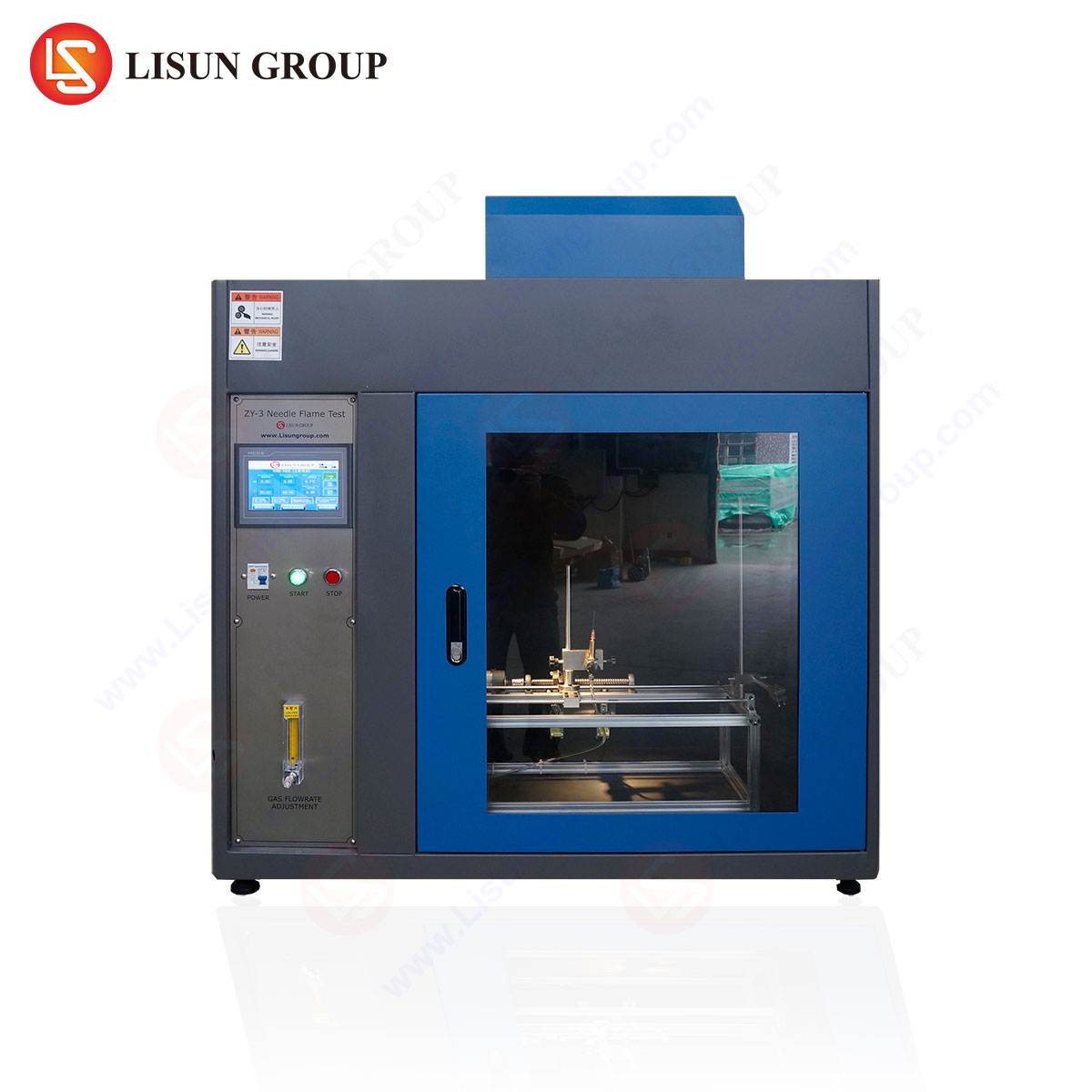
Q1: What is the primary difference between the Glow-Wire Test and a Needle-Flame Test?
Both assess fire hazard, but their simulation intent differs. The Glow-Wire Test simulates thermal stress from an overheated or glowing component in contact with a material. The Needle-Flame Test (IEC 60695-11-5) simulates a small, localized flame that may result from a fault condition, applying a direct flame to the specimen. The former is a contact heating source; the latter is a small, open flame.
Q2: Can the LISUN ZRS-3H be used for testing finished products, or only material samples?
The LISUN ZRS-3H is designed to test both. The standard includes provisions for testing end-products, sub-assemblies, and flat material samples. The adjustable specimen holder and application mechanism allow for the secure positioning of complex product geometries, such as switch enclosures, appliance housings, or connector assemblies, in accordance with the relevant product standard’s requirements.
Q3: How often does the glow-wire apparatus require calibration, and what does it involve?
Calibration frequency should follow the laboratory’s quality procedure, typically every 12 months or after a certain number of tests or any maintenance. Critical calibration involves verifying the temperature reading system using pure metals or calibrated thermocouples, and checking the application force (1.0 N ± 0.2 N). The LISUN ZRS-3H facilitates this with designed-in calibration points and routines to ensure ongoing compliance with IEC 60695-2-10’s accuracy requirements.
Q4: For a new product, how do we determine the correct test temperature (e.g., 750°C vs. 850°C)?
The test temperature is not chosen arbitrarily but is mandated by the specific end-product safety standard applicable to your device (e.g., IEC 60335-1 for appliances). These standards assign test severities based on the component’s function, location, and the potential severity of an overheating fault. A critical component carrying mains voltage or near a heat source typically requires a higher test temperature than a decorative, non-current-carrying part.
Q5: What are the key advantages of a digitally controlled system like the LISUN ZRS-3H over older analog systems?
Digital PID control provides superior temperature stability (±2°C during dwell time), faster heating ramps, and precise reproducibility. It eliminates guesswork and manual potentiometer adjustments, reducing operator error. Integrated data logging and recall functions aid in audit trails and report generation. Enhanced safety features, such as over-temperature protection and guarded test chambers, are also more reliably implemented in modern digital systems.