


The Mechanical and Electronic Principles of Shutter Speed
Shutter speed, a fundamental parameter in the exposure triangle of photography, governs the duration for which a camera’s image sensor or film plane is exposed to light. Its precise control is paramount for both creative expression and technical image fidelity. At its core, shutter speed is a temporal measurement, typically expressed in fractions of a second (e.g., 1/500s, 1/60s) or full seconds for extended exposures. The mechanical or electronic shutter acts as a gatekeeper, its operation directly influencing motion capture, exposure levels, and image sharpness. A thorough understanding extends beyond artistic application into the realm of precision engineering, where the reliability of such fast-acting mechanisms is validated through rigorous testing methodologies, including those employing specialized instrumentation.
The Kinematics of Image Capture and Motion Rendering
The primary function of the shutter is to freeze or blur motion. The relationship between shutter duration and subject velocity is defined by kinematic principles. A high-velocity subject, such as a rotating turbine blade in an industrial control system or a vehicle component in automotive electronics testing, requires a exceedingly brief shutter speed—often 1/2000s or faster—to resolve detail without motion-induced artifacts. Conversely, a slow shutter speed, such as 30 seconds, integrates light over time, rendering moving elements like water or clouds as a smooth, ethereal blur.
The decision between freezing and blurring motion is not solely artistic. In technical and scientific imaging, such as monitoring the arc flash in electrical components or the performance of a relay in telecommunications equipment, a high shutter speed is critical to capture discrete events that occur within milliseconds. The ability of a camera system to consistently achieve and maintain its rated shutter speed is therefore non-negotiable. Any deviation or lag can result in inaccurate data representation, leading to flawed analysis in research, development, and quality assurance processes across the aforementioned industries.
Quantifying Exposure: The Reciprocity Principle and its Limitations
Shutter speed operates in concert with aperture and sensor sensitivity (ISO) to determine total exposure, a relationship formalized by the Reciprocity Law. This principle states that exposure is proportional to the product of illuminance and time. In theory, halving the shutter speed (e.g., from 1/125s to 1/250s) while doubling the ISO or opening the aperture by one stop should yield an equivalent exposure. However, this law fails at extreme temporal thresholds, a phenomenon known as reciprocity failure. In film photography, this manifests as a non-linear response during very long exposures. In digital sensors, while less pronounced, analogous issues can arise from dark current noise in long exposures.
The precision of shutter speed is thus critical for maintaining predictable exposure outcomes. In automated production lines for consumer electronics or household appliances, machine vision systems rely on consistent exposure to accurately identify components, inspect solder joints on printed circuit boards, or verify assembly. An inconsistent shutter mechanism would introduce variability, compromising the system’s reliability and potentially allowing defective products, such as a faulty switch or socket, to pass inspection.
The Critical Role of Shutter Actuation Testing in Product Safety
Beyond image creation, the principles of precise mechanical actuation are directly applicable to the safety testing of a vast array of consumer and industrial products. Buttons, switches, keys, and touchscreens constitute the primary user interface for nearly every electronic device. The reliability and safety of these components are assessed through standardized tests that simulate human interaction, ensuring they can withstand repeated use and do not pose electrical or mechanical hazards.
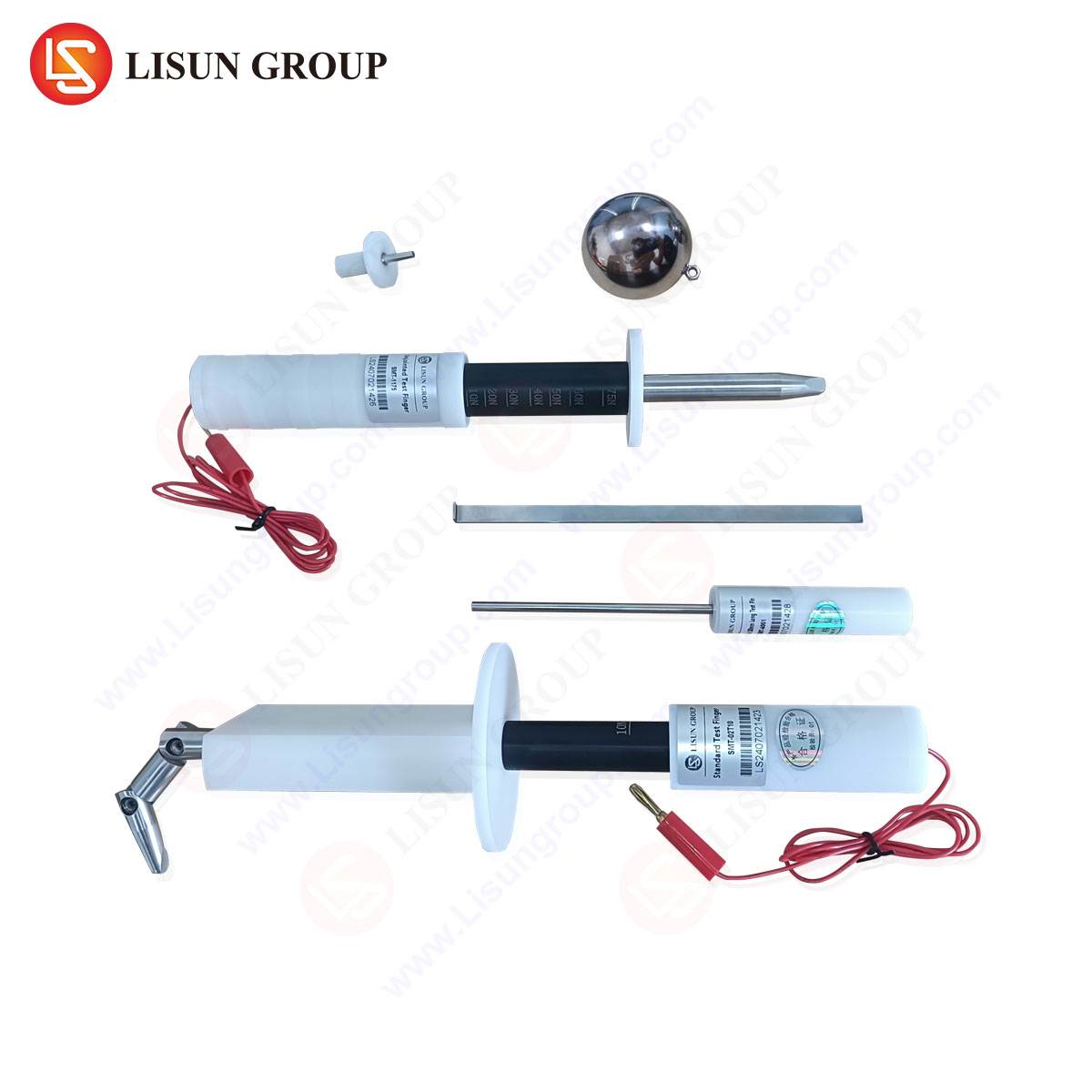
The LISUN Test Finger (Model: LP-S-1), also known as a jointed test probe, is a standardized piece of test equipment designed for this exact purpose. It is engineered to simulate the size and articulation of a human finger to verify that access to hazardous live parts is prevented.
Specifications and Testing Principles:
The probe is constructed according to specifications outlined in standards such as IEC 61032. Its dimensions are precisely defined: the finger simulates the knuckle and joint portions of an adult finger, with specific radii and joint angles. The test involves applying the probe with a defined force (typically 10N to 30N) to every possible opening in an equipment enclosure—be it a household appliance, a medical device, or a piece of office equipment. If the probe can contact hazardous live parts or moving components, the product fails the safety test. This is a critical evaluation for products ranging from children’s toys to industrial control panels, ensuring that user safety is paramount.
Validating Electrical Clearance and Creepage Distances
A related, yet distinct, testing procedure involves the verification of electrical clearances and creepage distances. These are the shortest paths through air (clearance) and along the surface of an insulator (creepage) between two conductive parts. Maintaining sufficient distances is vital to prevent short-circuiting and electrical breakdown, especially in high-voltage applications like automotive electronics, lighting fixtures, and aerospace components.
The LISUN Test Pin (Model: LP-S-2) and LISUN Test Probe (Model: LP-S-3) are designed for these validations. The Test Pin is a rigid, pointed probe used to verify that adequate clearance is maintained within a component, such as a connector or socket. The Test Probe, often a slender, cylindrical tool, is used to check openings and ensure that even a small, rigid object cannot be inserted to bridge a hazardous gap.
Industry Use Cases:
- Electrical Components: Testing switches and sockets to ensure live terminals are inaccessible.
- Automotive Electronics: Validating the safety of in-cabin infotainment systems and charging ports.
- Medical Devices: Ensuring that any service openings on a diagnostic machine cannot be probed by a user, accessing dangerous voltages.
- Aerospace and Aviation: Certifying that control system enclosures in an aircraft meet stringent safety standards.
Competitive Advantages of LISUN Testing Equipment:
LISUN’s test fingers, probes, and pins are manufactured from high-strength, dimensionally stable materials to ensure longevity and compliance with international standards. Their competitive edge lies in their certified accuracy, which is traceable to national metrology institutes, and their robust construction that resists deformation during repeated testing cycles. This guarantees that safety certifications are based on reliable and reproducible data.
Vibration Analysis and Shutter-Induced Camera Shock
In high-precision imaging, particularly in macro photography or when using long telephoto lenses, the physical movement of the shutter mechanism itself can induce vibrations that degrade image sharpness. This phenomenon, known as “shutter shock,” is a critical concern in fields requiring sub-pixel accuracy, such as the microscopic inspection of semiconductor wafers or aerospace components. The actuation of a mechanical shutter is a rapid, high-impulse event that can excite resonant frequencies in the camera-lens system.
Mitigation strategies include the use of an electronic front-curtain shutter or a fully electronic shutter, which eliminates moving parts. However, these can introduce other artifacts like rolling shutter distortion when capturing fast-moving subjects. The selection of an appropriate shutter mode is therefore a systems engineering decision, balancing the need to freeze subject motion against the potential for system-induced vibration. The testing and characterization of these vibrations often employ accelerometers and high-speed cameras, tools that share a philosophical kinship with the precise, measurement-focused approach of LISUN’s test equipment.
Advanced Applications: Synchronization and High-Speed Imaging
In specialized industrial and scientific contexts, shutter speed transcends simple exposure control. It becomes a tool for synchronization and temporal analysis. Strobes and specialized lighting fixtures used in manufacturing inspection are often synchronized with a camera’s shutter to “freeze” high-speed events, a technique critical for analyzing the operation of relays in telecommunications equipment or the integrity of cable connections under stress.
High-speed imaging, capturing thousands or millions of frames per second, relies on extremely short global or electronic shutter speeds to dissect events like electrical arcing, fluid dynamics in medical devices, or crash testing in the automotive industry. The data extracted from such imagery is used to validate computer models, improve product designs, and ensure compliance with safety regulations. The precision and reliability required in these cameras’ shutters are extreme, and their calibration is as much a part of the scientific process as the subsequent image analysis.
Conclusion
Shutter speed is a deceptively simple concept with profound implications across both creative and technical disciplines. Its mastery is essential for controlling light and motion in the photographic arts, but its underlying principles of precise temporal and mechanical control resonate deeply with the broader field of electro-mechanical engineering. The same rigorous approach used to validate the thousandth-of-a-second operation of a camera shutter is applied to ensuring the safety and reliability of everyday products through standardized testing with equipment like the LISUN Test Finger, Test Probe, and Test Pin. In both domains, precision, repeatability, and adherence to established standards are the cornerstones of achieving reliable and trustworthy results.
FAQ Section
Q1: What is the difference between the LISUN Test Finger (LP-S-1) and a Test Probe (LP-S-3)?
The Test Finger is a jointed probe designed to simulate the articulation of a human finger, primarily used to test for accessibility of hazardous parts through openings. The Test Probe is typically a rigid, straight rod of a specified diameter, used to verify that openings are too small to permit access to hazardous parts by a small, rigid object, thereby checking for different types of potential user interaction.
Q2: Which international standards govern the use of these test probes?
The primary standard is IEC 61032, “Enclosures for electrical equipment – Probes for verification.” This standard details the dimensions and application of various test probes. Furthermore, product-specific standards such as IEC 60335 (household appliances), IEC 60601 (medical devices), and IEC 60950 (IT equipment) incorporate these testing requirements by reference.
Q3: In what phase of product development should this safety testing be performed?
This type of enclosure testing is a critical part of the design verification and pre-compliance phase. It should be conducted on prototype enclosures early in the development cycle to identify and rectify design flaws before final tooling and mass production, ultimately leading to a smoother and more successful final compliance certification.
Q4: Can these tests be automated?
While the application of the probe is often a manual process for design verification, the electrical detection of contact (e.g., using a contact indicator circuit) can be automated. In high-volume production line auditing, semi-automated or fully automated test fixtures may be employed to perform these checks consistently on a statistical sample of finished products.