


Understanding the Figure 10 Test Bar: A Foundational Instrument for Hazard-Based Safety Engineering
Introduction to the Figure 10 Test Bar and Its Regulatory Genesis
The evaluation of electrical and electronic equipment for safety hazards is a discipline governed by a framework of international standards, primarily the IEC 61032 and its regional derivatives such as UL 61032 and EN 61032. These documents provide a codified methodology for assessing the protection of persons against access to hazardous live parts, mechanical hazards, and the ingress of solid foreign objects. Central to this methodology is the use of standardized test probes, which simulate various parts of the human body or common objects. Among these, the Figure 10 test bar, often referred to as the “jointed test finger,” occupies a critical position. It is not merely a tool but a calibrated artifact that embodies a specific philosophical approach to safety: the simulation of a child’s finger probing an enclosure. Its design, dimensions, and application force are precisely defined, making it an indispensable instrument for compliance engineers, product designers, and certification bodies across a vast spectrum of industries.
Deconstructing the Geometrical and Mechanical Specifications
The efficacy of the Figure 10 test bar stems from its rigorous dimensional and mechanical specifications, which are non-negotiable for valid testing. As per IEC 61032, Figure 10, the probe is designed to simulate the finger of a young child. Its key specifications include a diameter of 12 mm for the finger-like tip, a length of 80 mm for the proximal segment, and a second, 30 mm segment connected via a joint that allows for a 90° articulation in one plane. This joint is crucial, as it enables the probe to simulate the natural curling motion of a finger exploring an opening.
The standard mandates that the test be conducted with a force of 10 N ± 1 N. This specific force is a risk-assessed value, deemed sufficient to simulate persistent probing without being excessive. Furthermore, the probe must be constructed from metal to ensure electrical conductivity for live-part testing and sufficient rigidity for mechanical assessment. The tip is rounded to a specific radius to prevent unrealistic gouging while maintaining the simulation’s integrity. Any deviation from these parameters—a slightly undersized joint, an incorrect tip radius, or an uncalibrated force application—can invalidate test results, leading to non-compliance or, conversely, a false sense of security.
The Testing Principle: Simulating Real-World Probing Scenarios
The fundamental principle behind the Figure 10 test bar is hazard-based safety engineering through simulation. The test procedure is methodical. The probe is applied to every opening, grille, slot, or joint in an equipment enclosure with the specified 10 N force. It is manipulated through its full range of articulated motion to search for potential access paths to hazardous parts. The assessment has two primary facets:
- Electrical Hazard Assessment: The probe is connected to an indicator circuit, typically a low-voltage (e.g., 40-50V) supply in series with a visible or audible indicator. If the probe contacts a hazardous live part during the test, the circuit is completed, and the indicator activates, signifying a failure. This directly tests protection against electric shock.
- Mechanical Hazard Assessment: Even if electrical contact is not made, the probe’s ability to penetrate an opening is assessed. If the probe can access moving parts like fans, gears, or belts, or contact parts that could fragment, it constitutes a mechanical hazard failure. The test also verifies that the probe does not bypass interlock switches or depress safety-release mechanisms in an unsafe manner.
This dual-purpose testing ensures that enclosures provide a holistic barrier, not just an electrical one. It answers the critical question: Can a probing finger, as simulated, create a dangerous condition?
Industry-Specific Applications and Risk Mitigation
The universality of the probing hazard makes the Figure 10 test bar relevant across virtually all sectors manufacturing physical products with enclosures.
- Household Appliances & Consumer Electronics: From toasters and blenders to game consoles and routers, these devices are in environments accessible to children. Test points include ventilation slots, button surrounds, battery compartment lids, and seams between plastic housings.
- Electrical Components & Lighting Fixtures: Switches, sockets, circuit breakers, and LED drivers must prevent finger access to live terminals or uninsulated conductors. For lighting, the interface between the luminaire body and the diffuser, or openings in track lighting systems, are common test areas.
- Automotive Electronics & Industrial Control Systems: While in vehicle cabins, infotainment systems, charging ports, and control panels are within reach. In industrial control cabinets, even though access may be restricted, standardized operator interfaces, door seals, and cable gland entries must be evaluated.
- Medical Devices & Telecommunications Equipment: Patient-facing devices like monitors or infusion pumps, and network equipment in offices, must prevent accidental contact. The test ensures that service panels or ventilation grilles do not compromise safety.
- Toy and Children’s Products Industry: This is a paramount application. The test bar directly validates that toy battery compartments, speaker grilles, or joints in plastic toys cannot be penetrated by a child’s finger, preventing access to small batteries or pinching hazards.
- Aerospace and Aviation Components: For in-cabin entertainment systems, control panels, and galley equipment, the test ensures no hazardous access during normal operation or foreseeable misuse, contributing to overall cabin safety.
Introducing the LISUN Test Finger, Test Probe, and Test Pin System
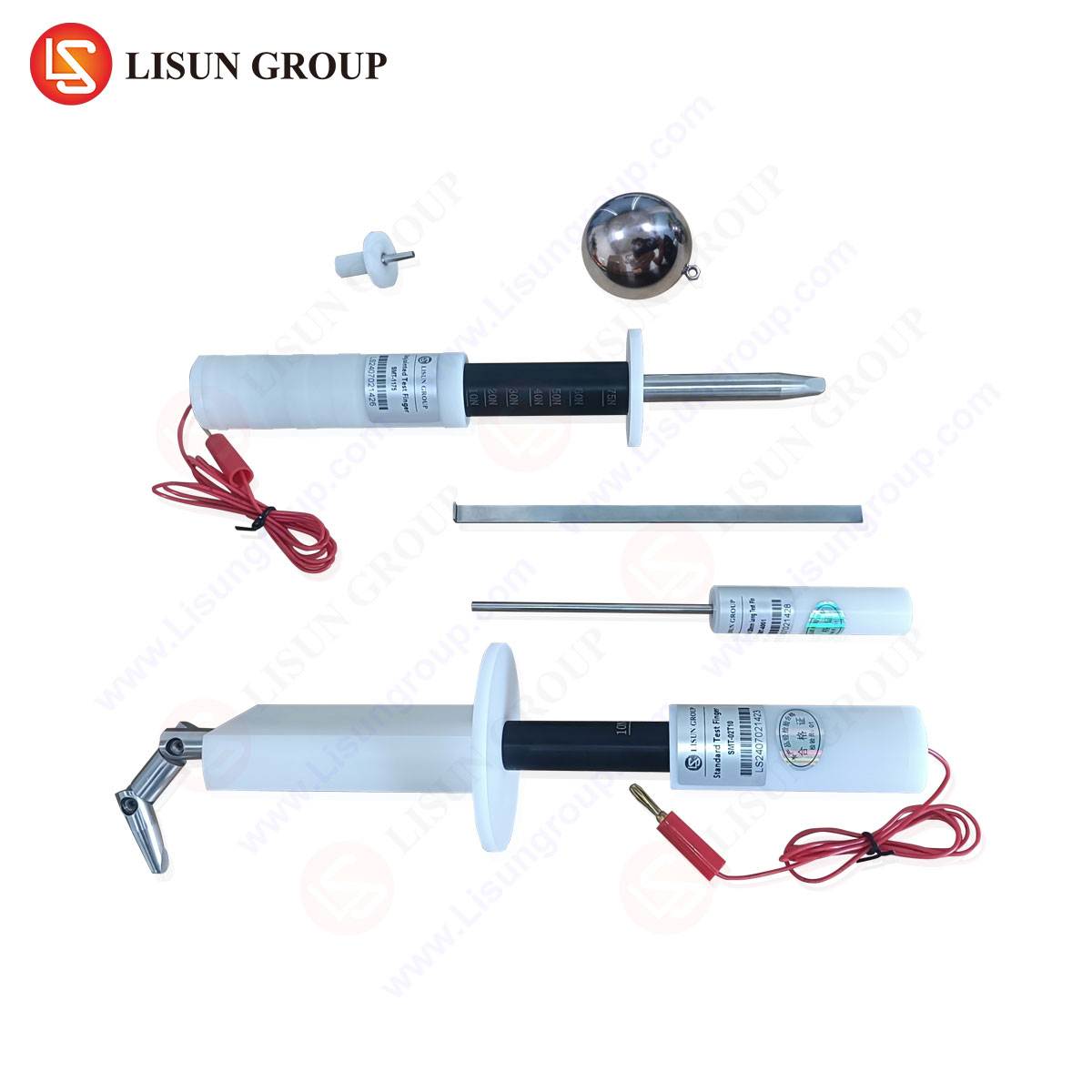
To execute these critical assessments with precision and reliability, the selection of test equipment is paramount. The LISUN Test Finger, Test Probe, and Test Pin system is engineered to meet and exceed the exacting requirements of IEC/UL/EN 61032, providing a comprehensive solution for safety evaluation laboratories.
The system is comprised of individual, meticulously manufactured probes corresponding to the standard’s figures. The LISUN Test Finger (Figure 10) is the centerpiece, fabricated from high-strength, conductive metal with a precisely machined joint and tip radius. It is designed to articulate smoothly at 90° with minimal play, ensuring consistent application and repeatable results. The probe is typically supplied with an insulated handle incorporating a force gauge or is compatible with a standardized test apparatus that applies the mandated 10 N ± 1 N force.
Specifications and Competitive Advantages:
- Material Compliance: Constructed from specified metals for optimal conductivity, durability, and corrosion resistance.
- Dimensional Fidelity: CNC-machined to tolerances stricter than the standard requires, guaranteeing geometric accuracy.
- Calibrated Force Application: When integrated into the LISUN testing apparatus, the system provides a calibrated and verifiable 10 N application force, eliminating operator-induced variability.
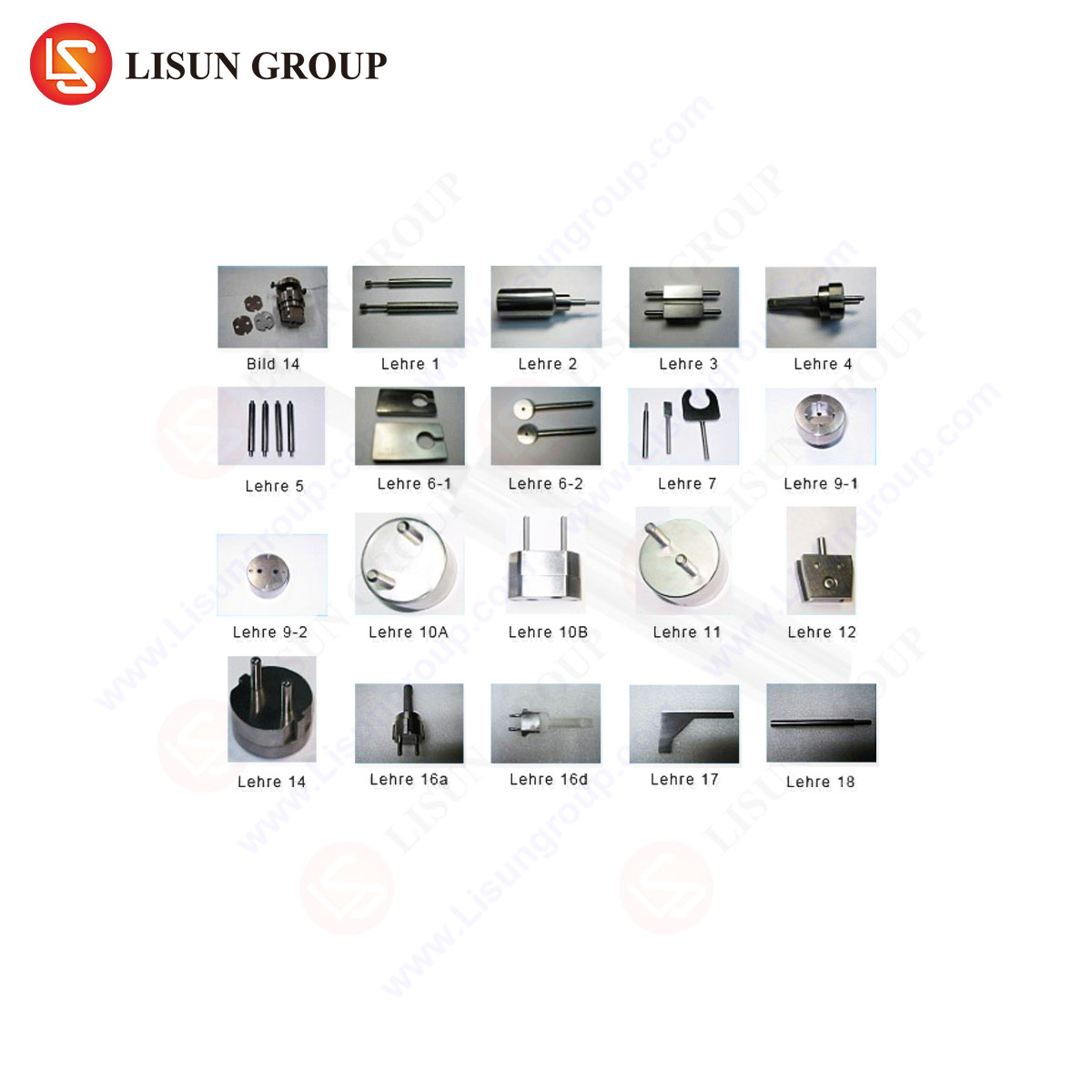
- Complete Ecosystem: LISUN offers the full suite of probes (e.g., Figure 11 test pin, Figure 12 spherical probe for object ingress, Figure 13 long probe) ensuring a single-source solution for all IEC 61032 tests.
- Traceability and Certification: Each probe is supplied with documentation traceable to national standards, a critical requirement for accredited testing laboratories and certification processes.
The competitive advantage lies in this combination of precision, completeness, and traceability. Inconsistent or out-of-specification probes can lead to contentious certification outcomes, product recalls, or, worst-case, field failures. The LISUN system mitigates this risk by providing laboratory-grade instrumentation.
Integration with Broader Testing Standards and Protocols
The Figure 10 test bar does not operate in isolation. Its application is often a gateway test within larger safety standards. For instance:
- IEC 62368-1 (Audio/Video, Information & Communication Technology Equipment): Explicitly references IEC 61032 for hazard-based safety engineering (HBSE) evaluations of energy sources.
- IEC 60335-1 (Household Appliances): Uses the test finger to verify protection against access to live parts and moving components.
- IEC 60598-1 (Lighting Fixtures): Mandates its use for testing accessibility of live parts through openings.
- IEC 60601-1 (Medical Electrical Equipment): Applies the probe for testing patient and operator enclosures.
A typical testing protocol begins with a visual inspection for obvious openings, followed by the systematic application of the Figure 10 probe. If the probe penetrates, subsequent tests with smaller probes (like the Figure 12 sphere or Figure 13 long probe) may be required to assess protection against ingress of tools or wires. Data recording is essential, noting the force applied, the angle of probe entry, and the specific component contacted.
Consequences of Non-Compliance and Design Implications
Failure to pass the Figure 10 test has severe ramifications. From a regulatory standpoint, it prevents the acquisition of necessary safety certifications (CE, UL, CCC, etc.), barring the product from key global markets. Legally, it exposes manufacturers to liability in the event of injury. Financially, it can trigger costly redesigns, production delays, and recall campaigns.
Therefore, intelligent design for compliance is imperative. Design engineers must consider the test probe during the CAD phase. Strategies include:
- Designing ventilation slots with baffles or honeycomb structures with gaps less than 12 mm in any orientation.
- Ensuring adequate creepage and clearance distances behind openings.
- Using reinforced seams and interlocking joints that cannot be pried open by 10 N of force.
- Positioning interlocks and service-access mechanisms so they cannot be actuated by the test finger.
Conclusion
The Figure 10 test bar is a deceptively simple tool that enforces a profound safety principle. It translates the abstract concept of “finger-safe” into a quantifiable, repeatable engineering test. Its standardized form is the universal language of enclosure safety, bridging diverse industries from children’s toys to aerospace interiors. As technology evolves, with devices becoming smaller and more integrated, the challenge of designing compliant enclosures only intensifies. Utilizing precision instruments like the LISUN Test Finger system ensures that this fundamental assessment is performed with the accuracy and reliability that modern product safety demands, ultimately serving the paramount goal of protecting users from harm.
Frequently Asked Questions (FAQ)
Q1: Can a product pass if the test finger touches an insulated wire or a component with basic insulation?
A: No. The test is designed to probe for access to hazardous live parts. A part is considered hazardous if its voltage exceeds safety extra-low voltage (SELV) limits. Contact with basic insulation, which is a single layer of protection, is typically deemed a failure, as the insulation could be compromised by the probing action. The probe must not contact any part that could become live under single-fault conditions.
Q2: How often should a Figure 10 test probe be calibrated or verified?
A: For accredited laboratories, calibration should be performed annually or in accordance with a documented quality procedure. Frequent visual inspections for damage (e.g., burrs on the tip, looseness in the joint) should be conducted before each use. Dimensional accuracy, joint articulation, and the applied force (if using an integrated apparatus) are the key parameters for calibration.
Q3: Is the 10 N force applied as a pushing force or a pivoting/angling force?
A: Both. The standard requires that the probe be pushed into the opening with 10 N. Subsequently, while maintaining contact and force, it must be angled or pivoted through its full 90° range of motion to simulate a finger “feeling around” inside the opening. This dual-action test is critical for finding indirect paths to hazards.
Q4: Our product has a removable cover for service. Does this need to be tested with the cover removed?
A: Testing is performed under conditions of “as delivered” and “as intended for use.” If the cover is intended to be removed by a user or service personnel using a tool, the standard often differentiates between “user-access” and “tool-access” areas. The cover itself, when in place, must be tested. The area underneath may be subject to different probe tests (e.g., a test pin simulating a tool) depending on the standard’s specific requirements for service access.
Q5: What is the difference between the Figure 10 test finger and the Figure B test finger from older standards?
A: The Figure 10 probe (from IEC 61032) is the contemporary, internationally harmonized version. The Figure B probe was specified in older editions of standards like IEC 60598-1. While similar in concept, they have different dimensions and force requirements (Figure B used 30 N or 50 N in some versions). Current compliance almost universally requires the use of the IEC 61032 Figure 10 probe. It is essential to verify which standard and edition is applicable to the product under test.