


The Role of the IEC 61032 Steel Rod Φ2.5mm Dynamometer in Product Safety Verification
The relentless pursuit of product safety in the global marketplace necessitates a rigorous framework of standardized testing methodologies. Among the most critical evaluations is the assessment of protection against access to hazardous live parts, a fundamental requirement across countless electrotechnical domains. The international standard IEC 61032, “Protection of persons and equipment by enclosures – Probes for verification,” provides the definitive specification for a suite of test probes designed to simulate potential access by human body parts or external objects. Within this suite, the Steel Rod Φ2.5mm Dynamometer, often referred to as the “test pin,” represents a specialized tool for evaluating the integrity of enclosures against penetration by small, rigid objects. This article provides a comprehensive technical examination of this device, its governing principles, and its critical application in ensuring compliance and safeguarding end-users.
Defining the Geometrical and Mechanical Parameters of the Test Pin
The IEC 61032 test probe 12, the formal designation for the Steel Rod Φ2.5mm Dynamometer, is characterized by its precise and unforgiving geometry. As its name implies, the primary element is a cylindrical steel rod with a diameter of 2.5 millimeters (±0.05mm). The tip of this rod is engineered to a specific configuration: a hemisphere on the end of the cylinder. This geometry is not arbitrary; it is designed to replicate small, rigid items like tool bits, wires, or pins that might inadvertently come into contact with electrical equipment during use, maintenance, or as a result of tampering.
The “Dynamometer” component of its name refers to the integrated force-measuring system. The standard prescribes the application of a calibrated force to the probe during testing, typically 1 N ± 0.1 N for basic protection and 10 N ± 1 N for increased safety, or as specified by an end-product standard. The dynamometer ensures that this force is applied consistently and measurably, eliminating operator-induced variability. The device must be capable of indicating when the specified force is being applied, allowing the tester to determine whether the probe penetrates an opening under that exact load. The material composition, typically a hardened steel, is specified to ensure sufficient rigidity and resistance to deformation, guaranteeing that the probe itself does not fail during the test, which would invalidate the results.
The Underlying Testing Principle: Probing for Weaknesses
The fundamental principle behind the use of the Φ2.5mm test pin is the simulation of a mechanical stress test on an equipment enclosure. The objective is unambiguous: to verify that under a defined mechanical force, a hazardous live part cannot be contacted. The test procedure involves applying the probe to every opening, joint, vent, or gap in the equipment’s enclosure that is deemed accessible without the use of a tool.
The test is conducted in two primary phases. First, the probe is applied with the standard test force (e.g., 1 N). If it does not contact a live part, the equipment passes for “basic protection.” Second, for applications requiring a higher degree of safety, the test is repeated with a higher force (e.g., 10 N or even 30 N as specified in standards like IEC 60601-1 for medical equipment). The probe must not enter a protected volume containing hazardous live parts or uninsulated moving parts. A “hazardous live part” is defined as a part that can constitute a risk of electric shock or electrical burn. The test’s binary outcome—either the probe contacts a hazardous part or it does not—provides a clear, repeatable, and standardized metric for compliance.
LISUN‘s Implementation of the IEC 61032 Test Probe System
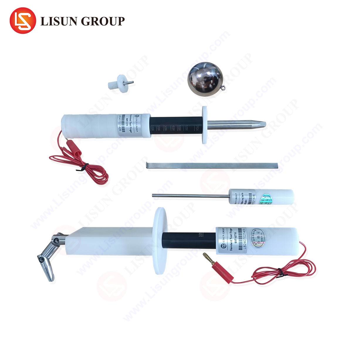
Manufacturers of testing equipment, such as LISUN, produce precision-engineered kits that include the full range of IEC 61032 probes, including the Test Finger (probe 11), the Test Probe (probe 13, often a slim finger), and the critical Test Pin (probe 12). The LISUN Test Finger, Test Probe, Test Pin kit is designed for laboratory and production-line use, embodying the exacting requirements of the standard.
Specifications and Competitive Advantages:
The LISUN Test Pin is manufactured from high-grade, hardened stainless steel to prevent wear and ensure long-term dimensional stability. The dynamometer mechanism is calibrated to a traceable standard, providing an accuracy of typically ±0.1 N, which is crucial for reproducible results across different testing facilities. The handle is ergonomically designed to allow for precise application without interfering with the force reading. A competitive advantage of the LISUN system lies in its comprehensive calibration certification, which is provided with each device, detailing its conformity to the geometries and force thresholds stipulated in IEC 61032. Furthermore, LISUN often offers these probes as part of a modular system that can be integrated with automated test fixtures, a significant benefit for high-volume manufacturers in industries like consumer electronics and automotive components.
Cross-Industry Application Scenarios and Use Cases
The application of the IEC 61032 Steel Rod Φ2.5mm Dynamometer is vast, touching nearly every sector that produces electrical or electronic equipment.
Electrical Components and Industrial Control Systems: In this domain, components like terminal blocks, circuit breakers, and contactors are scrutinized. The test pin is applied to the openings around terminal connection points. A failure here could allow a metal tool or stray wire to bridge a live terminal to earth or another phase, creating a short-circuit or shock hazard. Similarly, industrial control panels must be tested to ensure that ventilation slots or seams between door and frame cannot be penetrated by a rigid object that might contact internal busbars.
Household Appliances and Consumer Electronics: For products such as power supplies, kitchen blenders, or gaming consoles, the test pin checks openings for audio jacks, ventilation grilles, and battery compartments. A child might insert a pin or a paperclip into a small opening; the test verifies that such an action will not result in contact with a live part on the main printed circuit board.
Automotive Electronics and Aerospace Components: The harsh environments in these industries demand robust protection. Connectors for in-vehicle infotainment systems or flight control modules must be designed so that their mating interfaces cannot be probed with a 2.5mm object, preventing short circuits from metallic debris or improper handling during assembly. The test is often performed at the higher 10 N or 30 N force level to simulate vibration and incidental impact.
Lighting Fixtures and Telecommunications Equipment: LED drivers, street light controllers, and network router enclosures feature numerous vents for thermal management. The test pin ensures that these vents are designed with baffles or are of a small enough gauge to prevent the ingress of a rigid rod that could damage internal components or create an electrical hazard.
Medical Devices and Toy Safety: These are among the most stringent applications. According to IEC 60601-1, medical electrical equipment must prevent access to hazardous live parts with the test probe applied with a force of up to 30 N in some cases. For toys, standards like IEC 62115 mandate the use of the test pin to verify that batteries cannot be short-circuited by a child inserting a metallic object, and that no live parts are accessible from the outside of the toy.
Cable and Wiring Systems: Connectors and sockets are primary targets for this test. A standard AC power socket must be designed so that it is impossible to insert a 2.5mm pin and make contact with a live pin while the protective earth pin is already engaged, a scenario the test pin is designed to simulate.
Interpreting Test Results and Compliance Nuances
A successful test outcome is straightforward: the probe, under the specified force, does not penetrate the enclosure to the extent that it contacts a hazardous live part. However, interpretation can involve nuance. For instance, if the probe passes through an opening but is stopped by an internal barrier (e.g., an internal PCB shield or an insulated sheath), the design may still be deemed compliant, provided the barrier is reliably fixed and provides equivalent or better protection than the outer enclosure. The standard often differentiates between “adequate clearance” and “adequate creepage distance.” A probe might not physically touch a part, but if it reduces the air clearance to below the required minimum, the design may still fail the safety requirements. Therefore, the test is not merely a physical check but an integral part of a holistic safety assessment involving electrical insulation coordination.
Comparative Analysis with Other IEC 61032 Probes
The Φ2.5mm test pin serves a distinct purpose compared to its counterparts in the IEC 61032 arsenal. The LISUN Test Finger (probe 11) simulates a human finger, testing for the risk of electric shock from larger openings. The LISUN Test Probe (probe 13) is a jointed finger that can simulate access to deeper, more recessed hazards. The following table illustrates their distinct roles:
| Probe | Simulated Object | Primary Application | Typical Force |
|---|---|---|---|
| Test Finger (11) | Adult Finger | Basic protection against shock from large openings. | 10 N ± 1 N |
| Test Probe (13) | Child’s Finger / Small Tools | Access to deeper hazards through smaller openings. | 10 N ± 1 N |
| Test Pin (12) | Wires, Pins, Tools | Protection against penetration by rigid objects. | 1 N / 10 N / 30 N |
A comprehensive safety evaluation requires the sequential or selective application of all relevant probes, as a product might pass the test finger check but fail when subjected to the more penetrating test pin.
Frequently Asked Questions (FAQ)
Q1: What is the consequence if our product fails the IEC 61032 test pin evaluation?
A failure indicates a non-compliance with safety standards, which can prevent product certification (e.g., CE, UL, CCC) and market entry. From a technical standpoint, it identifies a design flaw that poses a real-world risk of electric shock, fire, or equipment damage. Remedial actions include redesigning the enclosure to include smaller vent holes, adding internal barriers, or improving the insulation of internal live parts.
Q2: How often should the LISUN Test Pin dynamometer be calibrated?
Calibration intervals depend on usage frequency and quality control system requirements (e.g., ISO 17025). For most commercial testing laboratories, an annual calibration is standard practice. However, if the device is used heavily or subjected to mechanical shock, more frequent verification is recommended to ensure the applied force remains within the specified tolerance.
Q3: Our product’s standard references both a 1 N and a 10 N test force for the test pin. Which one should we use?
The applicable force is dictated by the specific clause within the end-product standard. Typically, 1 N is used for “basic insulation” and accessibility under normal conditions. The 10 N (or higher) force is applied for “supplementary insulation” or to simulate greater mechanical stress, such as deliberate tampering or conditions of increased safety. You must consult the specific safety standard for your product category to determine the correct test condition.
Q4: Can a plastic enclosure that flexes under the test force lead to a false failure?
Yes, enclosure flexure is a critical consideration. The test must be conducted in a way that simulates the worst-case scenario. If the enclosure deforms under the 1 N force, creating a new opening, the test should be repeated while applying a force to the enclosure itself to simulate this deformation. Many product standards have specific clauses addressing the testing of flexible or deformable materials to account for this phenomenon.