


Understanding the IEC Needle Flame Test Procedure for Electrical Equipment Safety
Introduction to Fire Hazard Assessment in Electrical Products
The proliferation of electrical and electronic equipment across domestic, commercial, and industrial environments has necessitated the development of rigorous safety standards to mitigate fire risks. Internal faults, component failures, or external thermal insults can generate small ignition sources capable of propagating into hazardous fires. Traditional large-scale flame tests, while valuable for assessing fully developed fires, often fail to accurately simulate the initial ignition phase from a small, localized fault. Consequently, the International Electrotechnical Commission (IEC) developed the needle flame test, standardized under IEC 60695-11-5, to provide a reproducible method for evaluating the fire hazard presented by electrotechnical products and their sub-assemblies when subjected to a small, defined flame. This procedure is not a measure of a material’s inherent flammability but rather a functional assessment of a product’s ability to resist ignition and limit flame spread from a simulated internal fault condition.
Foundational Principles and Objectives of the Needle Flame Test
The core objective of the IEC 60695-11-5 test is to ascertain whether a small flame, applied to a test specimen under defined conditions, will cause a progressive fire. The test simulates a low-energy ignition source, such as that from an overheated or arcing component, a failing connection, or an overloaded circuit board track. The fundamental principle involves applying a standardized needle flame, produced by a specific burner and fuel mixture, to a predetermined point on the specimen for a stipulated duration. The specimen’s behavior is then meticulously observed during and after flame application. Key parameters assessed include the duration of any sustained flaming, the extent of flame spread, the production of burning or molten droplets that could act as secondary ignition sources, and the time to self-extinguishment. The pass/fail criteria are typically based on these observations, often specifying maximum allowable flaming times and limiting the extent of damage, thereby ensuring that a minor fault does not escalate into a system-level fire.
Detailed Apparatus and Calibration Requirements
The integrity of the needle flame test is contingent upon precise apparatus specification and rigorous calibration. The test apparatus comprises several critical components. The burner itself is a tube with a specified orifice diameter, typically fed with a mixture of 99% purity butane gas at a controlled flow rate to produce a flame of defined height and temperature profile. A standardized verification procedure, involving a copper block calorimeter, is mandated to calibrate the flame’s thermal output, ensuring a consistent 1000°C ± 60°C at a designated measuring point. The specimen is mounted on a suitable support within a draught-protected enclosure lined with untreated surgical cotton to detect falling incendiary particles. The test laboratory must maintain controlled environmental conditions, usually 23°C ± 5°C and 50% ± 20% relative humidity, to ensure reproducibility. Precise timing devices, gas flow meters, and positioning jigs complete the setup, forming a system where variability is minimized to isolate the specimen’s fire response characteristics.
The LISUN ZY-3 Needle Flame Test Apparatus: Technical Specifications and Operational Fidelity
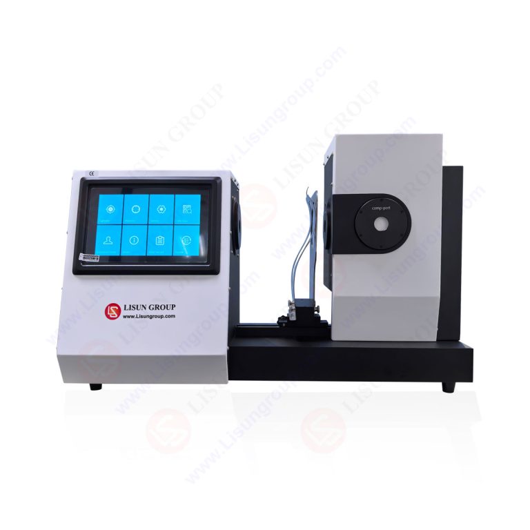
For laboratories and quality assurance departments requiring compliance with IEC 60695-11-5, the LISUN ZY-3 Needle Flame Test Apparatus represents a fully integrated solution engineered for precision and operational reliability. The apparatus is designed to meet the exacting dimensional and performance criteria outlined in the standard. Its core specifications include a high-precision stainless steel burner with a nominal orifice diameter of 0.5 mm, integrated with a fine-adjustment needle valve and a high-accuracy pressure-stabilized gas flow system to maintain a consistent butane supply. The unit features a digital timer with a range of 0-999.9 seconds for exacting control of flame application time, and an automated ignition system for operator safety and consistency.
The LISUN ZY-3 incorporates a calibrated copper block calorimeter as a standard accessory, facilitating routine flame verification in accordance with the standard’s calibration clause. The test chamber is constructed from stainless steel and includes a viewing window, internal cotton-indicator lining, and a specimen support table with adjustable height and angle positioning, allowing tests to be conducted in the most unfavorable orientation as required by end-product standards. Its digital interface provides intuitive control over test parameters, while its robust construction ensures long-term stability in a production or certification laboratory environment.
Procedural Execution: A Stepwise Analysis
The test procedure is methodical. Initially, the specimen is conditioned in the standard atmosphere. It is then mounted in its intended service position, or if that is undefined, in the position deemed most unfavorable for flame spread. The cotton indicator layer is placed beneath and around the specimen. Following apparatus calibration, the needle flame is applied to a preselected point on the specimen. The point of application is critical and is typically specified by the relevant product safety standard; it may be a specific component, a seam, a ventilation slot, or an area identified through fault condition analysis. The standard flame application time (Ta) is 30 seconds, though product committees may specify other durations (e.g., 10s, 60s, 120s) based on perceived risk.
Observations commence from the moment of flame application. Technicians record the duration of flaming combustion (ti) and after-flame time (te) for the specimen itself and for any ignited parts that may fall onto the cotton. The test concludes when all flaming and glowing has ceased, or after a predefined cutoff time. The specimen is then examined, and the extent of carbonized damage is measured. A successful outcome generally requires that after-flame times do not exceed specified limits (commonly 30 seconds), that flaming does not spread to the specimen’s edges, and that no cotton indicator is ignited by falling particles.
Industry-Specific Applications and Risk Mitigation
The needle flame test is invoked across a vast spectrum of industries where electrical safety is paramount. In household appliances, it is applied to internal wiring harnesses, motor windings, switch housings, and PCB assemblies to ensure a faulty thermostat or a seized motor does not ignite surrounding plastic enclosures. Automotive electronics manufacturers test connectors, control modules, and wiring conduits to prevent fires originating from the complex electrical systems in modern vehicles. For lighting fixtures, particularly those using polymeric materials for diffusers or housings, the test evaluates resistance to ignition from a failing ballast or LED driver.
Industrial control systems and telecommunications equipment employ the test for cable management systems, terminal blocks, and enclosure materials, safeguarding critical infrastructure. In medical devices, the flammability of non-metallic parts in devices like patient monitors or imaging systems is assessed to protect vulnerable environments. Aerospace and aviation components undergo stringent testing due to the catastrophic consequences of in-flight fires. The test is fundamental for electrical components like switches, sockets, and relays, as well as for the insulation and jacketing materials used in cable and wiring systems. Even office equipment (printers, power supplies) and consumer electronics (chargers, external power adapters) are subject to these evaluations to ensure safety in everyday use.
Interpreting Results and Integration into Safety Engineering
Test results provide qualitative and quantitative data that feed directly into the product safety engineering lifecycle. A failure indicates that the material selection, mechanical design (e.g., wall thickness, use of barriers), or component layout is insufficient to contain a small ignition event. Engineers may respond by specifying materials with higher comparative tracking index (CTI) or better flame-retardant properties, adding metallic shields or arc barriers, redesigning enclosures to isolate heat-producing components, or incorporating flame-retardant coatings. The test is often part of a larger suite of evaluations, including glow-wire, hot-wire, and arc resistance tests, to build a comprehensive fire hazard profile. Compliance with the needle flame test, as referenced in overarching safety standards like IEC 60335 (household appliances), IEC 60598 (lighting), or IEC 60950 (IT equipment), is frequently a mandatory requirement for achieving certification marks from bodies like UL, CSA, TÜV, or Intertek.
Advantages of the LISUN ZY-3 in Compliance Testing
The LISUN ZY-3 apparatus offers distinct advantages for organizations establishing or maintaining compliance testing capabilities. Its primary benefit is integrated compliance; the system is pre-configured to meet the mechanical and performance specifications of IEC 60695-11-5, reducing setup uncertainty. The inclusion of the calibration calorimeter and automated features minimizes operator-dependent variables, enhancing inter-laboratory reproducibility of results—a critical factor for certification. From an operational standpoint, its durability and straightforward interface reduce downtime and training overhead. For manufacturers across the aforementioned industries, deploying a reliable instrument like the ZY-3 facilitates robust internal quality control, enables rapid design validation during development cycles, and provides defensible data for third-party certification submissions, ultimately accelerating time-to-market for safer products.
Frequently Asked Questions (FAQ)
Q1: What is the primary difference between the IEC Needle Flame Test and the Glow-Wire Test?
A1: The tests simulate different ignition sources. The needle flame test uses a small, open flame (simulating a fire initiated by a burning component or external flame) to assess surface ignition and flame spread. The glow-wire test, per IEC 60695-2-10/11/12/13, uses an electrically heated element to simulate overheating from electrical faults (like poor connections or overloaded parts) and assesses ignition, flammability, and drip behavior under a thermal stress condition without an open flame.
Q2: Can the LISUN ZY-3 be used for testing to other related standards beyond IEC 60695-11-5?
A2: Yes. While its core design is optimized for IEC 60695-11-5, the fundamental principle of applying a small, calibrated flame makes it suitable for conducting tests specified in other national or industry standards that reference a similar methodology, such as certain clauses within UL standards or other technical specifications that call for a “needle-flame” or “small flame” test procedure. However, users must always verify the specific apparatus requirements of the target standard.
Q3: How often should the flame calibration on the ZY-3 apparatus be performed?
A3: According to IEC 60695-11-5, calibration should be performed at the start of a test series and at least every 4 hours during continuous testing. It is also recommended after any adjustment to the gas supply or burner, and as part of routine laboratory quality assurance protocols. The ZY-3’s included copper block calorimeter facilitates this routine verification.
Q4: What are the critical factors in preparing a specimen for needle flame testing?
A4: Specimens should be representative of the final product in terms of material, thickness, and, where possible, assembly. They must be conditioned in the standard laboratory atmosphere. Most importantly, the point of flame application must be selected based on the product standard’s stipulations or a fault hazard analysis, often targeting areas near heat-generating components, thin sections, joints, or ventilation openings.
Q5: In a product failure scenario, what do excessively long after-flame times or ignition of the cotton indicator typically indicate?
A5: These results indicate that the tested material or assembly possesses insufficient inherent resistance to flame propagation or produces incendiary droplets. This suggests a need for material reformulation (e.g., incorporating different flame retardants), design modification (increasing wall thickness, adding baffles), or component relocation to isolate potential ignition sources from vulnerable materials.