


Understanding Thermal Shock Testing: Principles, Methodologies, and Industrial Applications
Thermal shock testing represents a critical, accelerated reliability assessment within the broader domain of environmental stress screening. Its primary objective is to evaluate the robustness of materials, components, and finished products when subjected to extreme, rapid temperature transitions. Unlike gradual thermal cycling, thermal shock induces severe mechanical stresses due to differential expansion and contraction rates of dissimilar materials within an assembly. This process efficiently identifies latent manufacturing defects, design flaws, and material incompatibilities that could lead to premature field failures. The methodology is governed by a suite of international standards, including IEC 60068-2-14, MIL-STD-202G, and JESD22-A106, which define test parameters such as dwell times, transfer speeds, and temperature extremes. Industries ranging from aerospace to consumer electronics rely on this test to validate product integrity, ensure safety, and reduce warranty liabilities.
The Fundamental Physics of Thermal Stress Induction
At its core, thermal shock testing exploits the principles of thermal expansion and contraction. When a heterogeneous assembly—such as a printed circuit board (PCB) populated with integrated circuits, resistors, capacitors, and solder joints—experiences a rapid temperature change, each material responds according to its coefficient of thermal expansion (CTE). A significant CTE mismatch between, for example, a silicon die (CTE ~2.6 ppm/°C) and an FR-4 substrate (CTE ~14-18 ppm/°C in the X-Y plane) generates shear and tensile stresses at their interfaces. These stresses are concentrated at the weakest points, which are often microscopic in scale: solder interconnects, wire bonds, epoxy underfills, and plated through-holes.
The severity of the shock is a function of the temperature delta (ΔT) and the rate of change. A rapid transfer from +125°C to -55°C creates a ΔT of 180°C, imposing immense strain. Repeated cycling fatigues these connection points, potentially leading to crack initiation and propagation, delamination, and ultimately, electrical open or intermittent failure. The test, therefore, does not simulate a typical use environment but acts as a high-stress accelerant, compressing years of thermal fatigue into a manageable test duration. It is a pass/fail gate that separates robust designs from those vulnerable to inherent thermodynamic forces.
Methodological Implementations: Two-Zone versus Three-Zone Systems
Two principal apparatus configurations are employed to administer thermal shock: the two-zone (basket transfer) system and the three-zone (mobile chamber) system. Each presents distinct operational characteristics.
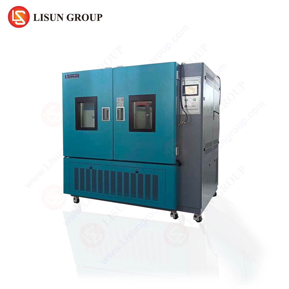
In a classic two-zone system, such as the LISUN HLST-500D Thermal Shock Test Chamber, the unit comprises separate high-temperature and low-temperature chambers. A mechanically driven basket shuttle transfers the test specimens between these zones with minimal delay, typically within 10 seconds as per many standard requirements. The HLST-500D exemplifies this design, featuring a vertical lift transfer mechanism that ensures swift, reproducible movement. The chambers are maintained at their target extremes, allowing for immediate exposure of the unit under test (UUT) to the new environment. This method is renowned for its high thermal transfer severity and is widely specified for component-level testing.
Conversely, a three-zone system integrates a high-temperature zone, a low-temperature zone, and a central test zone where the specimen remains stationary. Instead of moving the specimen, conditioned air is rapidly diverted to the test zone via a series of dampers and blowers. This approach is often favored for larger, heavier, or more fragile products where mechanical movement is undesirable. The choice between methodologies depends on the product’s mass, thermal mass, test standard specifications, and the desired failure mechanisms to be provoked.
Instrumentation Spotlight: The HLST-500D Thermal Shock Test Chamber
The LISUN HLST-500D is a precision-engineered two-zone thermal shock test chamber designed for rigorous compliance testing. Its specifications are tailored to meet the demanding protocols of military, automotive, and telecommunications standards.
Key Specifications:
- Temperature Range: High Temperature Chamber: +60°C to +200°C; Low Temperature Chamber: -10°C to -65°C (extendable to -80°C with optional LN2 cooling).
- Temperature Recovery Time: ≤5 minutes (from ambient to extreme set points).
- Transfer Time: ≤10 seconds (programmable).
- Dwell Time: Programmable from 0 to 999 hours, 59 minutes.
- Chamber Volume: 50 Liters per zone (standard).
- Control System: Microprocessor-based touchscreen controller with programmable cycles, real-time graphing, and data logging.
- Safety Features: Over-temperature protection, independent limit controllers, and mechanical door locks.
Testing Principle: The UUT is loaded onto the basket within the high-temperature zone. After a user-defined dwell period (e.g., 30 minutes), the basket swiftly transfers to the low-temperature zone for an equivalent dwell. This cycle repeats for hundreds or thousands of iterations. The controller meticulously records the internal chamber temperatures and the actual basket transfer times, ensuring the test profile’s fidelity. The rapid transition is the key stressor, and the HLST-500D’s mechanical design ensures this transition time is both minimal and consistent, a critical factor for reproducible, comparable results.
Competitive Advantages: The HLST-500D distinguishes itself through several engineered features. Its use of a high-efficiency German-made BITZER compressor in the low-temperature circuit enhances cooling performance and long-term reliability. The patented air circulation design within each chamber promotes exceptional temperature uniformity, typically within ±2.0°C. Furthermore, its robust stainless-steel construction and long-life heating elements are designed for continuous operation in demanding laboratory environments, minimizing downtime and total cost of ownership.
Industry-Specific Applications and Failure Mode Analysis
The application of thermal shock testing is ubiquitous across technology sectors. Its utility lies in its ability to precipitate failure modes relevant to each industry’s unique operational environments.
Automotive Electronics and Electrical Components: Modern vehicles contain hundreds of electronic control units (ECUs), sensors, and wiring harnesses. An engine compartment ECU may experience ambient temperatures from -40°C in winter to over +125°C near the engine block. Thermal shock testing on components like MOSFETs, connectors, and ceramic substrates validates resilience against solder joint fatigue, package cracking, and contact fretting. The HLST-500D can apply cycles from -65°C to +150°C to simulate these extreme transients, ensuring components survive not only operation but also the thermal inertia of startup from a deep cold soak.
Aerospace and Aviation Components: Avionics must function reliably after exposure to the rapid temperature changes associated with high-altitude flight or orbital cycles. Testing for these applications often involves extreme ranges (e.g., -65°C to +200°C) and is frequently conducted under vacuum conditions. While the HLST-500D is an atmospheric pressure chamber, it is extensively used for sub-assembly screening, such as testing the integrity of conformal coatings on PCBs, the seals of connectors, and the bonding of thermal interface materials before they are integrated into pressurized or vacuum-rated assemblies.
Telecommunications Equipment and Industrial Control Systems: Base station electronics, network switches, and PLCs are deployed in uncontrolled environments from desert sites to rooftop enclosures. Daily diurnal cycles, combined with internal heat generation from processors and power supplies, create repetitive stress. Thermal shock testing accelerates this aging process, identifying weak solder joints on large ball grid array (BGA) components, failures in multilayer ceramic capacitors (MLCCs), and delamination in high-density interconnect (HDI) PCBs. A test regimen might involve 500 cycles from -40°C to +125°C with 15-minute dwells.
Medical Devices and Consumer Electronics: Implantable devices, diagnostic equipment, smartphones, and laptops face both environmental exposure and heat generation from batteries and processors. For a sealed medical device, thermal shock can test the hermeticity of its casing and the stability of internal adhesive bonds. In a smartphone, it stresses the solder connections of the camera module, the flex cable bonds to the display, and the integrity of underfilled application processors. Failure in these tests can predict field issues like “black screen of death” or camera failure.
Lighting Fixtures and Household Appliances: LED-based lighting fixtures, particularly high-bay industrial or outdoor luminaires, experience significant thermal cycling as they are switched on and off. The CTE mismatch between the aluminum heat sink, the ceramic LED substrate, and the plastic housing is a prime target for thermal shock analysis. Similarly, the control boards in washing machines, ovens, and refrigerators are subjected to humidity and temperature swings. Testing ensures that relay contacts, power resistors, and display interfaces will not degrade prematurely.
Standards Compliance and Test Profile Development
Developing a meaningful thermal shock test profile is a deliberate process rooted in relevant industry standards. A generic profile is insufficient; the test must be tailored to the product’s lifecycle environment and failure mechanisms of concern.
Key Referenced Standards:
- IEC 60068-2-14 (Environmental testing – Part 2-14: Tests – Test N: Change of temperature): Provides fundamental guidance on test Na (rapid change) and test Nb (gradual change).
- MIL-STD-202G, Method 107 (Thermal Shock): A historically significant military standard defining stringent transfer times and temperature extremes.
- JESD22-A106 (Thermal Shock): The JEDEC standard for semiconductor devices.
- AEC-Q100 (for Automotive Integrated Circuits): References severe thermal shock as a qualification requirement.
- ISO 16750-4 (Road vehicles – Environmental conditions and testing for electrical and electronic equipment): Defines tests for climatic loads.
A test profile specifies the high and low temperature set points, dwell time at each extreme (sufficient for the UUT to reach thermal equilibrium), transfer time, number of cycles, and any electrical monitoring to be performed in-situ (e.g., continuity testing). For example, a profile for automotive under-hood sensors might be: High Temperature: +150°C, Low Temperature: -40°C, Dwell: 30 minutes, Transfer Time: <15 seconds, Cycles: 1,000. The UUT would be functionally tested at intervals (e.g., every 100 cycles) to detect parametric drift or catastrophic failure.
Data Interpretation and Failure Analysis Post-Testing
The conclusion of a thermal shock test sequence is not merely a pass/fail determination but the beginning of a critical analysis phase. Units that fail are subjected to meticulous failure analysis (FA) to determine the root cause. Techniques such as scanning acoustic microscopy (CSAM) can detect delamination inside IC packages without destructive disassembly. Cross-sectional analysis (microsectioning) of solder joints reveals crack propagation paths. Scanning electron microscopy (SEM) with energy-dispersive X-ray spectroscopy (EDS) can identify intermetallic compound growth or Kirkendall voiding.
The findings from this FA loop feed directly back into the design and manufacturing process. A pattern of solder joint cracks at a specific component location may indicate a need for a different solder alloy, a modified pad design, or the application of an underfill material. Delamination in a plastic-encapsulated microcircuit may point to issues with mold compound adhesion or die attach quality. Thus, thermal shock testing serves as a powerful diagnostic tool, driving continuous improvement in product reliability and manufacturing quality control.
Frequently Asked Questions (FAQ)
Q1: What is the critical difference between thermal shock testing and temperature cycling?
A1: The primary distinction lies in the rate of temperature change. Thermal shock testing employs an extreme rate of change, typically achieved by physically moving the test specimen between two pre-conditioned extreme chambers in seconds. Temperature cycling usually occurs within a single chamber where the temperature is ramped at a controlled, slower rate (e.g., 10°C per minute). Thermal shock induces more severe mechanical stress and is better for identifying gross material incompatities and latent defects, while temperature cycling better simulates slower, real-world operational cycles.
Q2: For the HLST-500D, how is the transfer time of ≤10 seconds measured and why is it important?
A2: The transfer time is measured from the moment the basket begins to leave the first chamber until the moment it is fully sealed within the second chamber. This metric is critically important because it directly defines the severity of the thermal shock. A longer transfer time allows the specimen to partially equilibrate with ambient air, reducing the effective ΔT and the induced stress. Consistent, sub-10-second transfers, as guaranteed by the HLST-500D’s vertical lift mechanism, ensure test rigor and reproducibility across different labs and test runs, which is essential for compliance with standards like MIL-STD-202G.
Q3: Can thermal shock testing be performed on powered, operating devices?
A3: While traditional thermal shock is typically performed on unpowered, passive devices, in-situ monitoring of basic continuity or insulation resistance is common. Fully powering and operating a complex device during the rapid transfer is technically challenging and not standard. Operational testing is usually conducted during temperature cycling or as a functional verification at ambient temperature between shock cycles. Specialized fixtures with quick-disconnect electrical feeds can be used, but they must not impede the rapid transfer mechanism.
Q4: How do I determine the appropriate high and low temperature set points for my product?
A4: Set points are derived from a combination of the product’s specification limits, its anticipated operational environment, and the relevant industry qualification standard. For example, a consumer electronics device might be tested at 0°C to +70°C based on its operational specs, while an automotive component would use -40°C to +125°C per AEC-Q100. The extremes should exceed the product’s rated limits to introduce a margin of safety. The product’s datasheet, applicable industry standards (e.g., ISO, IEC), and customer-specific requirements are the definitive guides.
Q5: What maintenance is required for a two-zone thermal shock chamber like the HLST-500D to ensure long-term accuracy?
A5: Regular preventive maintenance is crucial. Key activities include: periodic calibration of temperature sensors (typically annual), checking and cleaning condenser coils to maintain cooling efficiency, inspecting and lubricating the basket transfer mechanism to ensure consistent speed, verifying door seals for integrity to prevent temperature leakage, and checking the lubrication level in the compressors. Adhering to the manufacturer’s recommended maintenance schedule, as outlined in the HLST-500D manual, preserves measurement uncertainty, ensures compliance with quality systems like ISO/IEC 17025, and extends the operational lifespan of the chamber.