


Understanding UL Flammability Testing: A Technical Examination of Standards, Methodologies, and Critical Apparatus
Flammability testing constitutes a foundational pillar of product safety engineering, serving as a critical barrier against fire hazards in a technologically saturated world. Within this domain, standards developed by Underwriters Laboratories (UL) represent globally recognized benchmarks, particularly for electrical and electronic equipment. These tests are not mere procedural formalities but rigorous scientific evaluations designed to simulate real-world fault conditions, thereby quantifying a material or component’s resistance to ignition and its propensity for flame propagation. The implications of compliance are profound, spanning regulatory approval, market access, brand reputation, and, most critically, the prevention of injury and property damage. This article provides a detailed technical analysis of UL flammability testing, with a specific focus on glow-wire methodologies, their application across diverse industries, and the instrumental role of precision apparatus such as the LISUN ZRS-3H Glow-wire Test Apparatus in ensuring reliable and reproducible results.
The Regulatory and Normative Framework of UL Flammability Standards
UL flammability standards are developed through a consensus process involving manufacturers, testing laboratories, regulatory bodies, and consumer safety experts. They exist within a complex hierarchy, often harmonized with international IEC (International Electrotechnical Commission) standards, to facilitate global trade. Key standards include UL 94, “Tests for Flammability of Plastic Materials for Parts in Devices and Appliances,” and UL 746A, “Polymeric Materials – Short Term Property Evaluations.” UL 94 is arguably the most ubiquitous, classifying materials from least to most flammable: V-0, V-1, V-2 (vertical burn), HB (horizontal burn), and the more stringent 5VA/5VB (plaque testing). These classifications are not arbitrary but are determined by specific pass/fail criteria related to afterflame time, afterglow time, and whether dripping particles ignite a cotton indicator.
The philosophical underpinning of these tests, particularly the glow-wire tests outlined in standards like UL 746A, IEC 60695-2-10/11/12/13, and GB/T 5169.10-13, is to assess a product’s reaction to thermal stresses caused by overheated or glowing components under fault conditions. Unlike a direct flame, a glow-wire simulates an overheating electrical connection, resistor, or other element that may come into contact with non-metallic parts. This scenario is exceptionally relevant for enclosures, connectors, PCB substrates, and internal supports within electrical assemblies. Compliance with these standards is frequently a non-negotiable prerequisite for certification marks (UL, CE, etc.) and is mandated by product safety regulations in North America, Europe, and Asia.
Deconstructing the Glow-Wire Test Methodology
The glow-wire test is a sophisticated simulation that evaluates the ignition risk and fire-spreading behavior of solid electrical insulating materials or other non-metallic parts. The core principle involves heating a standardized Kanthal or Nichrome wire element, formed into a prescribed loop, to a precise temperature—typically ranging from 550°C to 960°C, depending on the required test severity (GWT: Glow-Wire Flammability Index, GWIT: Glow-Wire Ignition Temperature, or GWFI: Glow-Wire Flammability Index). This glowing element is then applied with a defined force (1.0 N ± 0.2 N) to the test specimen for a predetermined period (30 seconds).
The apparatus must meticulously control and monitor several interdependent variables to ensure test validity:
- Temperature Stability: The glow-wire tip temperature must be maintained within ± 10°C of the set point prior to application. This requires a high-precision thermocouple (Type K) embedded directly behind the tip and a responsive closed-loop temperature control system.
- Application Force: The mechanical assembly must apply and maintain the specified contact force consistently, without overshoot or decay, to ensure uniform thermal transfer.
- Timing Accuracy: The duration of application and subsequent observation periods (for afterflame and afterglow) must be electronically controlled to eliminate human timing error.
- Environmental Consistency: Tests are ideally conducted under controlled laboratory conditions to prevent drafts from affecting flame behavior, though some standards specify a defined airflow.
Observations recorded during and after the application include: time to ignition (if any), duration of any flames (afterflame time), duration of any glow (afterglow time), whether the specimen drips molten particles, and whether these particles ignite a tissue paper substrate. The pass/fail criteria are stringent. For instance, a material may pass the GWFI test if flames and glowing extinguish within 30 seconds after removal of the glow-wire, and if no ignition of the tissue paper occurs.
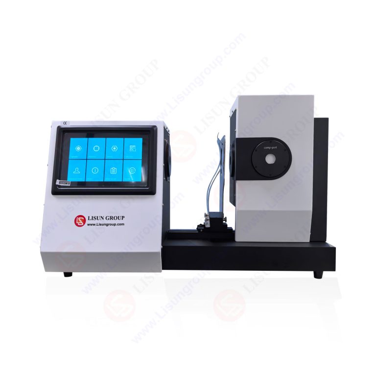
The LISUN ZRS-3H Glow-wire Test Apparatus: Engineering Precision for Compliance
To execute the methodologies described with the requisite fidelity, testing laboratories and quality assurance departments rely on specialized, calibrated equipment. The LISUN ZRS-3H Glow-wire Test Apparatus is engineered to meet and exceed the specifications of UL 746A, IEC 60695-2-10/11/12/13, and related national standards. Its design prioritizes accuracy, repeatability, user safety, and operational efficiency, addressing the common pain points of manual testing and less sophisticated apparatus.
Core Specifications and Functional Architecture:
- Temperature Control Range: 50°C to 1000°C, with a stability of ± 2°C at the set point, facilitated by a PID (Proportional-Integral-Derivative) digital controller. This wide range accommodates all standard test severities.
- Heating Element: A standardized Kanthal (FeCrAl) wire loop, conforming to dimensional requirements, ensuring consistent thermal mass and emissivity.
- Force Application: A precision solenoid system automatically applies the 1.0 N (± 0.2 N) contact force, eliminating manual pressure inconsistencies. The force is digitally calibrated and verifiable.
- Timing System: A fully automated digital timer controls the glow-wire application period (0-999.9s adjustable) and independently records afterflame and afterglow times, removing subjective judgment.
- Safety Features: The apparatus incorporates a transparent, mechanically interlocked safety viewing chamber to protect the operator from heat and potential fragments. An integrated fume extraction port allows for connection to external ventilation systems.
- Calibration: The system is designed for straightforward periodic calibration of temperature, force, and timing, which is essential for maintaining accreditation under ISO/IEC 17025 for testing laboratories.
Testing Principle Implementation: The ZRS-3H automates the critical phases of the test. The operator secures the specimen, sets the target temperature and application time, and initiates the sequence. The apparatus heats the wire, stabilizes the temperature, automatically moves the specimen into contact under the correct force, holds for the set time, retracts, and begins timing the aftermath. This automation drastically reduces inter-operator variability and enhances the reliability of the resulting data.
Industry-Specific Applications and Material Evaluation Imperatives
The universality of electrical and thermal energy makes glow-wire testing applicable across a vast industrial landscape. The specific test parameters and required performance levels are dictated by the product’s end-use environment, fault potential, and proximity to users or critical infrastructure.
- Household Appliances & Consumer Electronics: For products like food processors, televisions, and power adapters, internal components (motor housings, PCB mounts, connector bodies) are tested to ensure that a fault in a current-carrying part does not ignite the surrounding plastic, potentially leading to a cabinet fire.
- Automotive Electronics: The demanding environment of a vehicle—with high ambient temperatures, vibration, and potential for electrical transients—mandates rigorous testing for components like engine control unit (ECU) housings, sensor connectors, and infotainment system parts. Materials must often meet higher temperature thresholds (e.g., 750°C or 850°C GWFI).
- Lighting Fixtures: LED drivers, ballasts, and lamp housings can generate significant heat. Glow-wire testing evaluates the materials used in these enclosures and internal supports to prevent ignition from a failing component, such as a degraded capacitor or overloaded driver IC.
- Industrial Control Systems & Telecommunications Equipment: Control panels, PLC housings, server racks, and router enclosures are often installed in unattended or industrial settings. The requirement here is not only to prevent fire initiation but also to limit flame spread, as these devices may be part of critical operational or communication networks.
- Medical Devices & Aerospace Components: These sectors impose the most stringent requirements. Materials for ventilator housings, imaging equipment, or aircraft cabin electronics are subjected to high-severity glow-wire tests to ensure absolute reliability, as failure could be catastrophic. Testing often includes preconditioning (e.g., humidity aging) to simulate long-term material degradation.
- Electrical Components and Wiring Systems: Switches, sockets, circuit breakers, and cable insulation are directly in the current path. Glow-wire testing assesses the resistance of their insulating materials to ignition from poor connections or overloads, a primary cause of electrical fires in buildings.
Comparative Advantages of Automated Glow-Wire Testing Systems
The transition from manual or semi-automated test setups to fully integrated systems like the ZRS-3H represents a significant advancement in laboratory capability. The competitive advantages are measurable and impact both the quality and economics of compliance testing.
Data Integrity and Repeatability: Automated force application and digital timing eliminate the two largest sources of human error in manual testing. This results in lower standard deviations across test batches, producing more defensible and reliable data for certification submissions.
Enhanced Laboratory Efficiency: Automation reduces the active hands-on time required per test. Technicians can prepare the next specimen or perform other tasks during the automated heating and timing cycles. This increases testing throughput and optimizes skilled labor utilization.
Improved Operator Safety and Ergonomics: The interlocked safety chamber and automated sequence minimize operator exposure to high temperatures, potential flare-ups, and fumes. This creates a safer working environment and reduces risk.
Regulatory and Accreditation Alignment: For laboratories seeking or maintaining ISO/IEC 17025 accreditation, the ability to demonstrate calibrated, traceable, and automated control over all test parameters (temperature, force, time) is a substantial benefit during audits. The ZRS-3H’s design facilitates this demonstration.
Long-Term Cost of Ownership: While the capital investment is higher than for basic equipment, the reduction in test reruns (due to inconsistent manual results), increased throughput, and lower training burden contribute to a favorable total cost of ownership over the apparatus’s lifecycle.
Interpreting Test Results and Advancing Material Science
The output of a glow-wire test is more than a simple pass/fail notation. The quantitative data—time to ignition, afterflame duration, etc.—provides invaluable feedback to material scientists and design engineers. A material that barely passes at 750°C may be deemed unsuitable for a high-reliability automotive application, whereas one that shows no ignition at 850°C offers a greater safety margin. This data drives material selection, informs design modifications (such as adding flame-retardant barriers or heat sinks), and guides the formulation of new polymeric compounds.
Furthermore, testing is not performed in a vacuum. Materials are often preconditioned via UV exposure, humidity cycling, or thermal aging per UL 746B to simulate end-of-life performance. A material that passes a glow-wire test in its virgin state but fails after accelerated aging reveals a critical vulnerability that must be addressed. Thus, the glow-wire apparatus is a key tool in a holistic product safety and durability strategy, enabling proactive risk mitigation rather than mere retrospective compliance checking.
Conclusion
UL flammability testing, particularly the glow-wire methodology, is a sophisticated and essential discipline within product safety engineering. It translates abstract fire risks into quantifiable, standardized metrics that govern material selection and product design across virtually every sector of manufacturing. The integrity of this process is wholly dependent on the precision, reliability, and repeatability of the test apparatus employed. Advanced, automated systems like the LISUN ZRS-3H Glow-wire Test Apparatus represent the current state of the art, providing the necessary control over critical variables to generate trustworthy data. By ensuring rigorous compliance with international standards, such technology plays an indispensable role in safeguarding lives, property, and the continuity of modern technological infrastructure, ultimately upholding the very purpose of the safety standards themselves.
FAQ Section
Q1: What is the primary difference between the GWIT (Glow-Wire Ignition Temperature) and GWFI (Glow-Wire Flammability Index) tests, and how does the ZRS-3H accommodate both?
GWIT is the temperature 25°C above the maximum temperature at which a material does not ignite for 5 seconds or more during a 30-second application. GWFI is the highest temperature at which a material either does not ignite or, if it does, extinguishes within 30 seconds after removal of the glow-wire and does not ignite a tissue paper below. Both tests require precise temperature control and timing. The ZRS-3H accommodates them through its wide, stable temperature range (50-1000°C) and its automated, digitally controlled timing sequences for both the application and post-application observation periods, allowing it to be configured for either test protocol.
Q2: For a manufacturer of automotive electronic control units (ECUs), what specific glow-wire test criteria are typically required, and why?
Automotive ECUs, especially those in under-hood locations, are subject to extreme temperatures and vibration. Standards like ISO 20653 (ingress protection) and various OEM-specific specifications often require GWFI testing at 850°C or 960°C. This high severity simulates a worst-case overheating scenario. The material of the ECU housing and internal supports must not ignite, or must self-extinguish rapidly, to prevent a fire from propagating from a single faulty component. The ZRS-3H’s ability to reliably achieve and maintain these high temperatures with ±2°C stability is critical for valid testing in this sector.
Q3: How does the automated force application system in the ZRS-3H improve test reproducibility compared to manual methods?
Manual application of the 1.0 N force using weights or springs is prone to variation due to operator technique, friction in guide mechanisms, and difficulty in ensuring perfectly vertical application. The ZRS-3H’s solenoid-based system applies the force electronically and consistently for every test. This ensures uniform thermal contact between the glow-wire and the specimen, which is a fundamental variable affecting heat transfer and, consequently, ignition behavior. Eliminating this variability directly improves inter-laboratory and intra-laboratory reproducibility.
Q4: In the context of laboratory accreditation (ISO/IEC 17025), why is the calibration traceability of the ZRS-3H so important?
ISO/IEC 17025 requires that all equipment influencing test results be calibrated and that this calibration be traceable to national or international measurement standards (SI units). For the ZRS-3H, this means its temperature sensor (thermocouple), force application system, and timers must have documented calibration certificates from an accredited provider, establishing an unbroken chain of comparisons. This traceability provides confidence that the test results (e.g., “passed GWFI at 750°C”) are accurate, defensible, and globally recognized, which is essential for certified test reports used in regulatory submissions.
Q5: Can the ZRS-3H be used for testing non-standard specimen shapes, such as a complete small switch or connector?
Yes, within practical limits. While many standards specify standardized plaques (e.g., 60mm x 60mm), the end-product test clause in standards like IEC 60695-2-11 allows for testing of finished parts or sub-assemblies to simulate a real fault condition. The ZRS-3H’s specimen holder is designed to be adaptable. With appropriate fixturing or custom mounting plates designed by the user, irregularly shaped components can be securely held in the correct orientation for testing, provided the area to be tested can be properly presented to the glow-wire tip.