


Evaluating Electrical Safety Through Uninsulated Component Testing
The proliferation of electrical and electronic equipment across domestic, commercial, and industrial environments necessitates a rigorous, standardized approach to safety evaluation. Among the most critical assessments is the verification of protection against accessible hazardous live parts. This verification is formally conducted through Uninsulated Component Testing, a fundamental electrical safety test defined by international standards such as IEC 61032, IEC 60529, and their regional derivatives (e.g., UL, CSA, GB). The test’s objective is unambiguous: to determine whether a hazardous live part, which could cause electric shock, is accessible to a user under normal or foreseeable fault conditions. The methodology employs standardized test probes, often colloquially termed “test fingers,” to simulate human interaction with the equipment enclosure.
The Biomechanical Basis of Standardized Test Probes
The design of test probes is not arbitrary; it is a product of extensive anthropometric and biomechanical research. These tools are engineered to replicate the dimensions and probing capabilities of various parts of the human body—from a child’s finger to an adult’s hand or a tool held by a user. The goal is to create a repeatable, objective simulation of real-world access scenarios. A probe that is too lenient may fail to identify a genuine shock hazard, while an overly restrictive one could unjustly penalize safe designs. The specifications for joint articulation, applied force, and probe geometry are meticulously detailed in standards to ensure global consistency in safety evaluations. For instance, the simulation of a child’s finger must account for both size and the exploratory probing behavior typical of young users, a critical consideration for the Toy and Children’s Products Industry.
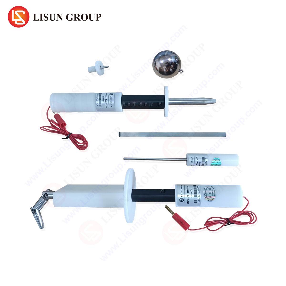
Instrumentation for Objective Access Verification: The LISUN Test Finger, Test Probe, and Test Pin
To execute Uninsulated Component Testing with the precision and repeatability demanded by certification bodies and quality assurance laboratories, specialized instrumentation is required. The LISUN Test Finger (IEC 61032 Probe 11-B), Test Probe (IEC 61032 Probe 13), and Test Pin (IEC 61032 Probe 12) represent a calibrated system for this purpose. These are not simple pieces of metal; they are measurement devices with strict tolerances.
The LISUN Test Finger (Probe B) is the most frequently employed tool, simulating an adult’s finger. Its design incorporates articulated joints that allow it to bend and probe in a manner mimicking natural finger movement. It is applied with a standardized force (typically 10 N ± 0.5 N) to every potential access point on an enclosure—openings, vents, seams, and gaps around controls. If the probe can contact a hazardous live part, or enter far enough to reduce electrical clearance to below mandated levels, the design fails the test. This is paramount for Household Appliances like food processors and for Consumer Electronics such as gaming consoles, where user interaction is frequent.
The LISUN Test Probe (Probe 13) simulates a slender object, like a wire or tool, that might be inserted into an opening. It is a rigid, straight probe of defined diameter used to verify protection against access by such objects. Its application is critical for Electrical Components like socket outlets and Industrial Control Systems with terminal compartments, where only tools should have access.
The LISUN Test Pin (Probe 12) represents a more rigid, pointed object. It is used to assess the strength and integrity of barriers, particularly in applications where deliberate forceful probing is a consideration, or to test openings in Lighting Fixtures and certain Office Equipment.
Table 1: Key Specifications of LISUN Standard Test Probes
| Probe Type | IEC 61032 Designation | Simulates | Typical Application Force | Primary Use Case |
| :— | :— | :— | :— | :— |
| Test Finger | Probe 11-B (Jointed Test Finger) | Adult finger | 10 N ± 0.5 N | General accessibility of live parts through openings. |
| Test Probe | Probe 13 (Test Probe) | Wire, slender tool | 1 N ± 0.1 N | Access to hazardous parts via small openings (e.g., socket slots). |
| Test Pin | Probe 12 (Test Pin) | Rigid, pointed object | 3 N ± 0.3 N | Strength of barriers; testing openings in luminaires. |
The competitive advantage of a calibrated system like LISUN’s lies in its traceable manufacturing tolerances and material compliance. The probes are constructed from materials with specified electrical and mechanical properties (e.g., insulating materials for non-conductive portions, hardened steel for pins), and their dimensions are verified against master gauges. This ensures that test results are not a function of tool variance but of the product design itself, a non-negotiable requirement for laboratories achieving ISO/IEC 17025 accreditation.
Testing Protocols and Failure Mode Analysis
The testing protocol is systematic. The Equipment Under Test (EUT) is de-energized and placed in its most unfavorable configuration for access—with removable covers off, as intended by the user, and adjustable parts positioned to maximize openings. The appropriate probe is then methodically applied. A crucial part of the test involves coupling the probe to a detection circuit. In the “signaling circuit” method, the probe is electrically connected to the hazardous live part inside the EUT via a low-voltage (e.g., 40-50V) supply in series with a visible or audible indicator. If the probe makes contact with a conductive part connected to this circuit, the indicator activates, signaling failure.
Failure modes are categorized. A direct failure occurs when the probe physically contacts a live part at mains potential. An indirect, but equally critical, failure occurs when the probe bridges a creepage or clearance distance, reducing it below the minimum values specified for the equipment’s working voltage and pollution degree. This is especially relevant for Telecommunications Equipment and Automotive Electronics operating in high-humidity or contaminated environments, where surface tracking could eventually lead to a breakdown.
Industry-Specific Applications and Risk Mitigation
The application of Uninsulated Component Testing varies significantly across sectors, reflecting differing use environments and risk profiles.
In Medical Devices, the consequences of electric shock are severe, potentially occurring to a patient who is physically compromised. Testing here is exhaustive, often employing not just the standard finger but also specialized probes to simulate medical tubing or connectors that may inadvertently contact enclosure openings.
Aerospace and Aviation Components must withstand extreme vibration and pressure differentials that can distort enclosures and create new access paths. Testing is performed not only in a static state but often as part of environmental stress sequences to verify integrity under operational conditions.
For Automotive Electronics, particularly under-hood components, the test must consider the presence of conductive fluids, road salt, and the potential for tools to slip during servicing. The Test Probe and Test Pin are vital for evaluating the robustness of IP-rated connector seals and housing interfaces.
The Lighting Fixtures industry relies heavily on the Test Pin (Probe 12) to evaluate the safety of lamp enclosures and track lighting systems, where a rigid object might be inserted into a bayonet or slot.
In Cable and Wiring Systems, testing focuses on terminations, connectors, and junction boxes, ensuring that even when a cable is pulled or twisted, live terminals remain inaccessible to a probing finger or tool.
Standards Harmonization and Regulatory Implications
Compliance with Uninsulated Component Test requirements is not optional; it is embedded in the fundamental safety standards for virtually every class of electrical equipment (e.g., IEC 62368-1 for AV/IT equipment, IEC 60335-1 for household appliances, IEC 60601-1 for medical devices). Regulatory frameworks such as the EU’s Low Voltage Directive and various national safety marks (UL, CCC, PSE) mandate demonstration of compliance, typically through testing by a Notified Body or certified laboratory.
The harmonization of probe specifications in IEC 61032 provides a global benchmark, though regional deviations exist. A competent testing laboratory must possess a full suite of probes that are regularly calibrated to ensure their geometry and articulation remain within standard-specified limits. The use of an out-of-specification probe can invalidate test results, leading to non-conformities during audits or, worse, the certification of an unsafe product.
Integrating Accessibility Testing into the Design Lifecycle
Forward-thinking manufacturers integrate accessibility analysis into the earliest stages of product design. Using CAD models and the digital dimensions of standard probes, engineers can perform virtual testing to identify and rectify potential access issues before prototyping. This proactive approach, known as Design for Safety (DFS), reduces costly redesigns and accelerates time-to-market. Physical verification with tools like the LISUN Test Finger series remains the definitive pass/fail criterion, but its use in the design validation phase confirms that theoretical protections function in practice, particularly for complex assemblies in Industrial Control Systems or Office Equipment with moving parts and ventilation labyrinths.
FAQ: Uninsulated Component Testing & Standard Probes
Q1: Can a product pass if the test finger touches an insulated wire inside the enclosure?
A: It depends on the insulation. If the wire is considered a “hazardous live part,” its insulation must meet functional requirements (e.g., withstand a specified dielectric strength test). Merely having a layer of plastic sleeving may not suffice. The test often includes a “paper strip” supplement: if a standard strip of paper can be inserted alongside the test finger and contact the part, the insulation is deemed inadequately guarded.
Q2: How often should test probes like the LISUN Test Finger be calibrated?
A: Calibration intervals are typically annual, aligning with quality system requirements (e.g., ISO/IEC 17025). However, frequency should be risk-based. Probes used daily in a high-throughput lab may require semi-annual verification, while those in occasional use might follow an annual cycle. Regular visual inspections for damage or wear are also mandatory before each use.
Q3: Is the test performed with the equipment powered on at operational voltage?
A: No. For obvious safety reasons, the accessibility test is performed de-energized using the low-voltage signaling circuit method described. The objective is to determine the potential for access. Subsequent dielectric strength or leakage current tests, performed at operational voltage, then validate the insulation systems of those parts that were determined to be accessible.
Q4: What is the difference between “accessible” and “live” part in this context?
A: A “live part” is any conductor intended to be at a potential different from earth during normal operation. A “hazardous live part” is one that can deliver a harmful shock under normal or single-fault conditions. The test determines if such a part is “accessible,” meaning it can be contacted by the standardized probe. A part may be live but not hazardous (e.g., Safety Extra-Low Voltage circuits), or it may be hazardous but rendered inaccessible by a properly designed enclosure.
Q5: Are there probes for testing resistance to access by small animals or insects?
A: While not typically called “Uninsulated Component Testing,” standards for certain equipment (e.g., outdoor enclosures) include probes to verify protection against ingress of solid foreign objects, which can include rodents. These are defined under IP Code testing (IEC 60529), using steel rods and wires of specific diameters. The philosophy is similar—using a standardized object to objectively verify a design’s protective characteristic.