


An Analytical Framework for Dimensional Verification of Plugs and Sockets: The Role of VDE 0620-1 Gauge 14
The global marketplace for plugs and socket-outlets is characterized by a complex tapestry of regional standards and stringent safety requirements. Ensuring compliance with these specifications is not merely a matter of market access but a fundamental imperative for user safety and product reliability. Within the European framework, the VDE 0620-1 standard represents a critical benchmark for the safety of plugs and socket-outlets. Central to the physical verification of these components is a specialized tool: the VDE 0620-1 Gauge 14. This article provides a detailed technical examination of the gauge’s function, its application within quality assurance protocols, and the specific capabilities of advanced testing systems, such as those manufactured by LISUN, which are engineered to deliver unparalleled precision in compliance verification.
Interpreting the Mandate of VDE 0620-1 for Pin Configuration
The VDE 0620-1 standard, published by the Verband der Elektrotechnik, Elektronik und Informationstechnik (VDE), meticulously defines the safety requirements for plugs, socket-outlets, and related devices. Its purview encompasses protection against electric shock, thermal effects, mechanical hazards, and the reliable connection of live parts. A pivotal aspect of this standard is the dimensional specification for plug pins and the corresponding socket-outlet receptacles. The Gauge 14, specifically, is engineered to assess the dimensional compliance of the contact tube apertures within a socket-outlet designed to accept a standard CEE 7/4 (Schuko) plug. Its primary function is to verify that the socket’s contact tubes will correctly engage with a compliant plug’s pins, ensuring sufficient contact pressure for electrical integrity while preventing the insertion of undersized or non-conforming pins that could lead to hazardous high-resistance connections or arcing.
The gauge is not a singular tool but a set of precisely machined probes, each designed to test a specific dimensional limit. The application of these gauges is prescribed in the standard’s clauses pertaining to mechanical construction and dimensional checks. For instance, the standard mandates that a socket-outlet must be designed such that it is impossible for a user to make contact with live parts. The Gauge 14 set includes probes that simulate attempts to breach this safety feature, verifying that shutters or other protective devices function as intended. The dimensional tolerances specified for these gauges are exceptionally tight, often in the range of a few hundredths of a millimeter, reflecting the critical nature of a secure electrical interface.
Deconstructing the Gauge 14 Dimensional Verification Set
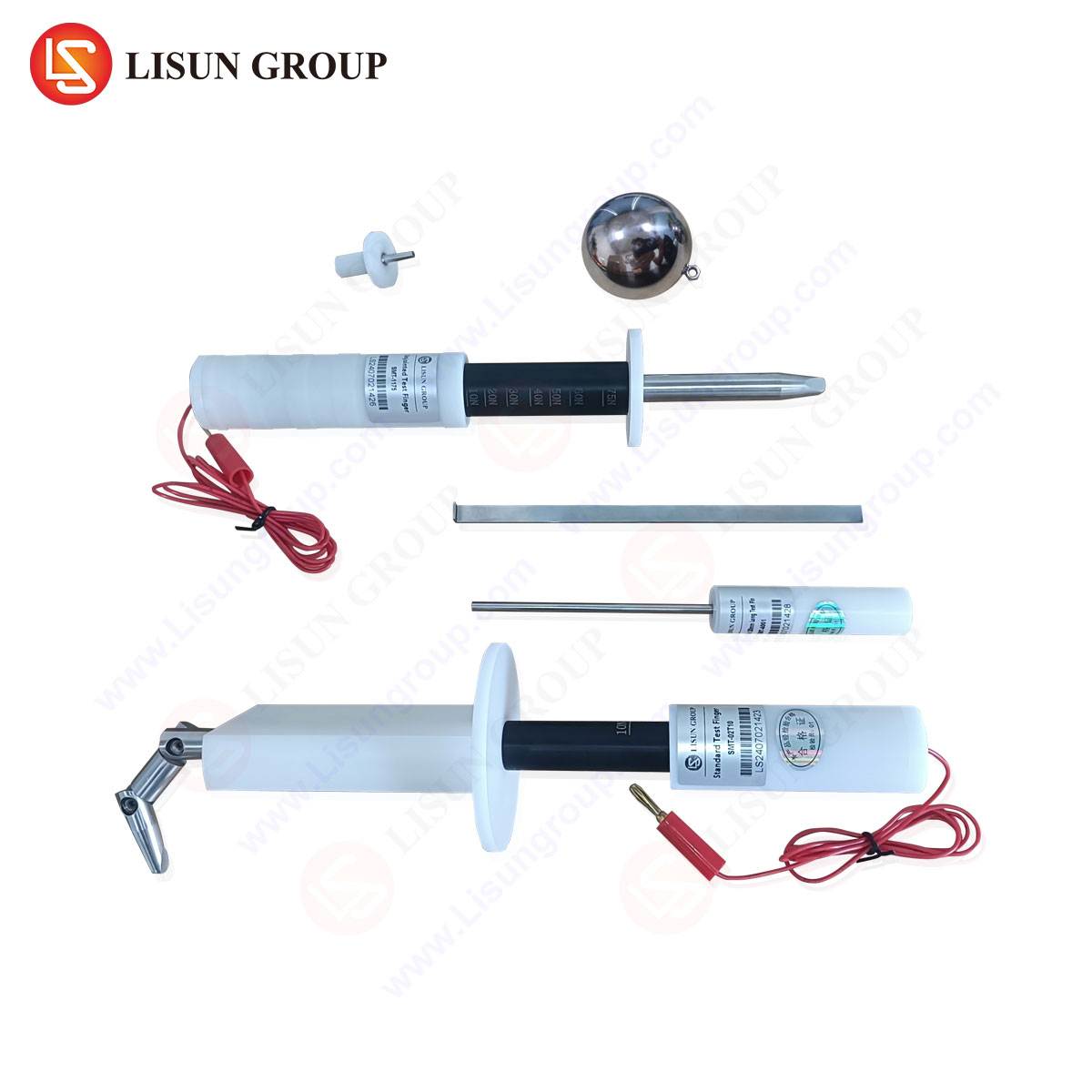
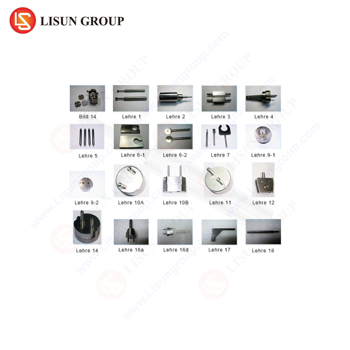
The VDE 0620-1 Gauge 14 set is a comprehensive kit comprising several individual gauges, each with a distinct verification purpose. A typical set includes gauges for checking the following parameters:
- Contact Tube Diameter and Depth: Probes of specified diameters and lengths are used to verify that the contact tubes are neither too narrow (preventing insertion) nor too wide (failing to provide adequate grip). A “GO” gauge of maximum permissible dimensions must enter the contact tube, while a “NO-GO” gauge of minimum permissible dimensions must not.
- Earth Contact Engagement: Specific gauges test the dimensions and placement of the earth contact clips, ensuring they will make reliable contact with the earth pins of a plug before the live pins are engaged, a fundamental sequence for safety.
- Shutter Mechanism Integrity: Perhaps one of the most critical safety checks involves the shutter mechanism. Gauges are designed to simulate single-pin insertion attempts. A compliant socket-outlet must prevent access to the live contact tubes when a probe is inserted into only the neutral or earth opening. The gauge applies a defined force to test the shutter’s resistance to being forced open, a direct test of its child-safety features.
- Pin Entry Profile and Alignment: Additional gauges check the alignment of the contact tubes and the geometry of the pin entry guides, ensuring that a plug can be inserted smoothly and without excessive force that could damage the socket or the plug.
The material composition of these gauges is typically a hardened, non-corrosive steel or an alloy with similar properties. This ensures dimensional stability over repeated use, resistance to wear that could alter critical measurements, and the necessary mechanical strength to apply the forces required by the standard without deforming.
Table 1: Exemplar Gauge Probes within a VDE 0620-1 Gauge 14 Set
| Gauge Designation | Primary Function | Critical Dimension(s) | Acceptance Criterion |
| :— | :— | :— | :— |
| Probe A (GO) | Verifies minimum contact tube diameter | 4.8 mm diameter | Must fully enter the contact tube |
| Probe B (NO-GO) | Verifies maximum contact tube diameter | 5.1 mm diameter | Must not enter the contact tube beyond a specified depth |
| Probe C (Shutter Test) | Tests shutter resistance to single-pin insertion | Simulated pin profile | Must not open the shutter when applied with a standard force (e.g., 1 N) |
| Probe D (Earth Contact) | Checks engagement depth of earth clip | Specific step profile | Must make/break contact at defined insertion depths |
The Integration of Gauge 14 in Automated Test Benches
While manual application of the Gauge 14 set is a valid verification method, it is subject to human error, inconsistency in applied force, and subjective interpretation of results. Modern manufacturing and quality control laboratories increasingly rely on automated test equipment to standardize the compliance verification process. Companies like LISUN have developed sophisticated testing apparatus that integrates the physical principles of the Gauge 14 into a fully automated, data-driven system.
A LISUN automated socket-outlet test system, for instance, employs a robotic actuator to precisely manipulate the individual gauge probes. The system is programmed to apply each probe with a repeatable force and trajectory, eliminating operator variance. Integrated sensors, including linear variable differential transformers (LVDTs) and load cells, provide quantitative feedback on parameters such as insertion depth, applied force, and mechanical resistance. This data is logged against the device under test (DUT), creating an auditable trail of compliance. The testing sequence is controlled by software that is pre-loaded with the exact dimensional and force parameters from VDE 0620-1, ensuring the test is performed to the letter of the standard.
The testing principle is one of pass/fail against digitally defined limits. For example, when testing the contact tube diameter, the system will drive the “GO” gauge probe and monitor the force-displacement curve. A successful pass is recorded only if the probe reaches the required depth without exceeding a maximum force threshold. Conversely, the “NO-GO” probe must be prevented from reaching the depth, and the system verifies this. This binary, sensor-based approach removes any ambiguity from the test outcome.
LISUN Gauges for Plugs and Sockets: Specifications and Metrological Assurance
The efficacy of any automated test system is contingent upon the quality and precision of its core components—the gauges themselves. LISUN manufactures its VDE 0620-1 Gauge 14 sets to exacting metrological standards, ensuring they serve as a true reference for compliance. The specifications for these gauges are derived directly from the latest revisions of the VDE 0620-1 standard, with tolerances that are significantly tighter than those required for the socket-outlets being tested. This practice of maintaining “gauge-maker’s tolerances” ensures that measurement uncertainty is minimized.
Key specifications for a LISUN Gauge 14 set include:
- Material: High-carbon chromium bearing steel (e.g., GCr15), hardened to 58-62 HRC (Rockwell C scale) for exceptional wear resistance.
- Dimensional Tolerance: Critical dimensions are held to tolerances of ±0.005 mm or finer, as dictated by the standard’s requirements.
- Surface Finish: A superior surface finish, typically better than Ra 0.2 µm, is achieved through precision grinding and polishing. This minimizes friction during testing and prevents the gauge from scratching or damaging the contact tubes of the socket-outlet under test.
- Traceability: Each gauge set is supplied with a certificate of calibration from an accredited metrology laboratory, providing traceability to national or international measurement standards.
The competitive advantage of utilizing a calibrated LISUN gauge set within an automated system is multifold. It provides manufacturers with a defensible and repeatable quality control process. It accelerates the testing cycle, enabling 100% inspection in high-volume production environments. Furthermore, the digital record-keeping inherent to these systems simplifies the process of obtaining and maintaining product certifications from bodies like VDE, TÜV, and other notified bodies.
Application in High-Volume Manufacturing and Certification Labs
The use of VDE 0620-1 Gauge 14 is mandated across two primary domains: end-of-line production testing in manufacturing facilities and type-approval testing in independent certification laboratories.
In a manufacturing context, a sample of socket-outlets from each production batch is subjected to Gauge 14 testing. Automated systems like those from LISUN are particularly valuable here, as they can be integrated directly into the production line. A fixture holds the socket-outlet, and the system executes the complete suite of gauge tests in a matter of seconds. Any failure immediately flags the unit and can trigger a root-cause analysis on the manufacturing process, such as a misaligned stamping die or a worn-out contact spring forming tool.
For certification laboratories, the Gauge 14 test is a non-negotiable part of the type-test sequence for any new socket-outlet design seeking a VDE mark. The test verifies that the design, in its submitted form, meets all dimensional safety requirements. The precision and documented calibration of the gauge set are paramount in this setting, as the test results form the basis for a legally recognized certification. The ability of automated systems to generate detailed test reports, complete with force-displacement graphs for each probe, provides certifiers with a higher degree of confidence in the submitted product’s conformity.
Mitigating Common Non-Conformities Identified by Gauge 14 Testing
Routine application of the Gauge 14 test frequently uncovers specific failure modes in socket-outlet production. A common non-conformity is the failure of the shutter test. This indicates that the internal shutter mechanism is either too weak, easily defeated by a single-pin insertion attempt, or is misaligned, allowing a probe to bypass it entirely. Another frequent issue is related to contact tube diameter. A “NO-GO” failure suggests that the contact tubes are too large, which will result in insufficient gripping force on a plug’s pins, leading to overheating under electrical load. Conversely, a “GO” failure indicates tubes that are too small, presenting a user with difficulty inserting a plug and potentially damaging both the plug and the socket.
The quantitative data from an automated test system provides invaluable diagnostic information. For example, if the force required to insert the “GO” gauge is consistently at the high end of the permissible range, it may indicate a trend towards tooling wear in the contact tube forming process, allowing for proactive maintenance before a full-blown non-conformity occurs. This transforms the quality control process from a reactive to a predictive one.
Frequently Asked Questions (FAQ)
Q1: How often should a VDE 0620-1 Gauge 14 set be recalibrated?
The recalibration interval depends on usage frequency and the quality control protocols of the facility. For high-volume manufacturing environments performing continuous testing, an annual recalibration is a typical industry practice. For laboratories performing intermittent type-approval testing, a biennial cycle may be sufficient. The calibration certificate supplied with the gauge set, such as those provided by LISUN, will often recommend a maximum interval, and this should be adhered to in order to maintain the integrity of test results.
Q2: Can a single Gauge 14 set be used to test socket-outlets from different manufacturers?
Yes, absolutely. The VDE 0620-1 Gauge 14 is a standard reference tool. Its dimensions are defined by the VDE 0620-1 standard, not by any specific manufacturer. Therefore, it is the universal instrument for verifying that any socket-outlet claiming compliance with the Schuko standard (CEE 7/4) meets the mandated dimensional and safety requirements.
Q3: What is the consequence of using a worn or out-of-calibration gauge set?
Using a compromised gauge set poses significant risks. A worn “NO-GO” gauge that is undersized could falsely pass a socket-outlet with oversized contact tubes, leading to a product with poor electrical contact being released to the market. Conversely, a worn “GO” gauge that is oversized could falsely fail a compliant socket-outlet, resulting in unnecessary production scrap and costly downtime for troubleshooting. Maintaining gauge integrity is fundamental to a reliable quality assurance system.
Q4: Beyond dimensional checks, what other tests are typically performed alongside the Gauge 14 verification?
The Gauge 14 test is part of a comprehensive suite of mechanical and electrical tests. It is commonly performed in conjunction with tests for electrical continuity, dielectric strength (hipot), grounding integrity, temperature rise under load, and mechanical durability (insertion/withdrawal cycle tests). Automated test stations often integrate several of these checks into a single, sequential routine for efficiency.
Q5: How does automated gauge testing improve upon manual testing?
Automated testing eliminates human factors such as inconsistent application force, subjective visual assessment, and potential for misreading results. It provides objective, quantifiable data (e.g., force in Newtons, displacement in millimeters) for every test, creates automatic and tamper-proof records for audit trails, and significantly increases testing throughput and repeatability, which is critical for modern manufacturing quality control.