


An Analytical Framework for Plug Retention Force Measurement in Accordance with VDE 0620-1
The integrity of the electrical connection between a plug and a socket-outlet is a foundational element of electrical safety. A compromised connection, characterized by insufficient physical retention force, can lead to a cascade of failure modes including intermittent power, arcing, localized overheating, and ultimately, fire hazard. To mitigate these risks, standardized testing protocols have been established globally. Among the most rigorous of these is the German VDE 0620-1 standard, which specifies precise methodologies for verifying the mechanical and electrical properties of plugs and socket-outlets. Central to the mechanical verification process is the quantitative measurement of plug extraction force, a parameter for which specialized instrumentation is required. This article provides a technical examination of the Plug Force Gauge, with a specific focus on systems designed for compliance with VDE 0620-1, and explores the implementation of such testing using LISUN Gauges for Plugs and Sockets.
Defining the Mechanical Interface: Plug Retention Force and Its Safety Implications
Plug retention force is the mechanical force required to disengage a plug from a socket-outlet under specified conditions. This force is generated by the complex interaction between the plug’s contact pins and the socket’s contact sleeves. An optimal force ensures a stable electrical path with low contact resistance, while simultaneously preventing accidental dislodgement due to minor cable strain or vibration. However, a force exceeding upper tolerance limits can cause mechanical wear on the socket contacts and pose a usability challenge, particularly for vulnerable users. Conversely, a force below the specified minimum threshold fails to maintain adequate contact pressure, leading to a high-resistance connection. This high-resistance junction becomes a point of significant I²R heating, which can degrade the insulating materials, oxidize the metal contacts, and initiate a thermal runaway condition. The VDE 0620-1 standard, therefore, delineates explicit minimum and maximum extraction force values that a product must meet to be certified for the German and broader European market, making its accurate measurement not merely a matter of quality control but a critical safety imperative.
Deconstructing the VDE 0620-1 Extraction Force Test Protocol
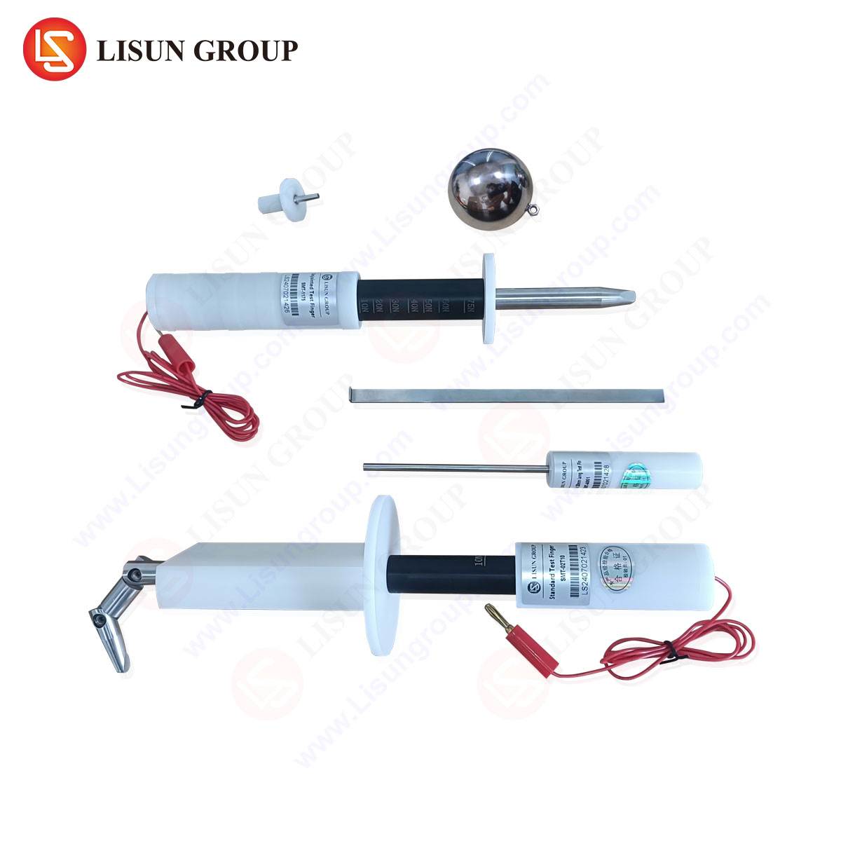
The VDE 0620-1 standard outlines a highly procedural and repeatable test method to evaluate plug retention. The test is not a single measurement but a sequence designed to simulate both initial product performance and endurance over a device’s operational lifespan. The procedure mandates the use of a standardized, geometrically defined test pin, often referred to as a “check gauge” or “test mandrel.” This pin is manufactured from a specified material, typically a hardened steel or brass, with a surface finish and dimensional accuracy traceable to national standards. The test sequence generally involves a series of engagements and disengements—a pre-conditioning cycle—followed by the force measurement on a new, unused socket, and subsequently, a post-endurance test measurement after the socket has undergone a specified number of mechanical operating cycles.
The actual force measurement is conducted by axially withdrawing the test pin from the socket contact at a controlled, constant speed. The maximum force recorded during this withdrawal is the extraction force. The standard specifies different force limits for different types of contacts (e.g., line, neutral, and earth contacts), recognizing that the earth contact, often being the first to make and last to break connection, may be subject to different mechanical design constraints. The test apparatus must therefore be capable of not only applying and measuring force with high precision but also of doing so in a perfectly aligned axial direction to prevent the introduction of bending moments that would invalidate the results.
Architectural Principles of a Modern Plug Force Gauge System
A contemporary Plug Force Gauge is an integrated electromechanical system engineered to automate and precisely control the test parameters mandated by standards such as VDE 0620-1. Its architecture can be deconstructed into several core subsystems, each fulfilling a critical function.
The mechanical drive system is responsible for generating the linear motion required to insert and extract the test pin. This is typically achieved using a precision ball screw or lead screw driven by a stepper or servo motor. The choice of motor is critical; it must provide smooth, cog-free motion to ensure a constant withdrawal velocity, as specified by the standard (e.g., 100 mm/min ± 10 mm/min). Any deviation from this constant speed can lead to dynamic force artifacts that do not reflect the true static friction of the contact interface.
The force sensing subsystem forms the metrological heart of the instrument. It employs a high-accuracy load cell, a transducer that converts an applied mechanical force into an electrical signal. For plug force testing, strain gauge-based load cells are predominant due to their excellent linearity, robustness, and high-resolution capabilities. The load cell must be selected with a capacity appropriate for the expected force range (typically 0-200 N for standard plugs and sockets) and must offer sufficient resolution to discern minute force variations. The load cell is mechanically integrated into the moving assembly, with the standardized test pin attached directly to it.
The control and data acquisition system encompasses the electronic hardware and software that orchestrate the test. A programmable logic controller (PLC) or embedded microprocessor sends command signals to the motor drive, initiating motion profiles. Simultaneously, it samples the analog voltage signal from the load cell at a high frequency, converting it into a digital force reading via an analog-to-digital converter (ADC). The software component provides the user interface for configuring test parameters—such as test speed, travel distance, and force limits—and for executing the test sequence. It also records the entire force-displacement curve, allowing for post-test analysis to identify phenomena such as stick-slip behavior or premature release.
LISUN Gauges for Plugs and Sockets: A System-Level Implementation
LISUN’s product line for plug and socket testing represents a comprehensive implementation of the principles described above, engineered specifically for compliance with international standards including VDE 0620-1, BS 1363, and IEC 60884-1. The LISUN LPS Series, for instance, is a fully automated solution that integrates the mechanical drive, force sensing, and control into a single, benchtop instrument.
Key Specifications of the LISUN LPS Series:
- Force Measurement Range: 0-200 N (configurable sub-ranges available).
- Force Resolution: 0.1 N or better, ensuring detection of subtle force differentiations.
- Displacement Accuracy: Controlled via a precision encoder, with a positioning resolution of 0.01 mm.
- Test Speed: Programmable from 10 to 500 mm/min, with a default setting for VDE 0620-1 compliance.
- Data Output: Real-time graphical display of the force vs. displacement curve, with automatic peak force capture and data logging for traceability.
- Test Pins: Supplied as a set of certified, hardened steel pins with geometries conforming to VDE 0620-1 and other major standards.
The testing principle is fully automated. The operator secures the socket-outlet in a dedicated fixture, selects the pre-programmed VDE 0620-1 test profile from the software, and initiates the sequence. The system automatically performs the required number of insertion/extraction cycles at the specified speed, recording the peak extraction force for each relevant contact (L, N, PE). The results are compared against user-defined pass/fail limits, and a comprehensive test report is generated. This level of automation eliminates operator-induced variability, a significant source of measurement uncertainty in manual or semi-automated test methods.
Industrial Application and Integration within Quality Assurance Regimens
The primary application for a VDE 0620-1 compliant Plug Force Gauge is within the quality assurance laboratories of manufacturers producing plugs, socket-outlets, and power strips. Its use spans multiple stages of the product lifecycle.
In Research and Development, engineers utilize the gauge to validate new contact designs and material pairings. By analyzing the detailed force-displacement curves, they can diagnose design flaws, such as incorrect contact spring geometry or suboptimal surface coatings, before committing to mass production tooling.
During Incoming Quality Control (IQC), manufacturers of finished assemblies use the gauge to verify the mechanical performance of socket components sourced from subcontractors. This ensures that incoming batches meet the required specification, preventing the cost and disruption of integrating non-conforming parts into final products.
The most critical application is in the Final Product Audit and Type Testing phase. Here, samples from production lines are subjected to the full battery of VDE 0620-1 tests, including the extraction force measurement, to provide ongoing assurance of compliance and to support the certification process with auditable data. The ability of systems like the LISUN LPS to store test profiles and results for hundreds of samples makes them indispensable for maintaining production quality records.
Comparative Advantages in Metrological Performance and Operational Workflow
When evaluated against legacy methods such as spring scales or simple push-pull gauges, automated systems like the LISUN gauges offer distinct competitive advantages that extend beyond mere compliance.
Metrological Fidelity: The elimination of human operator influence from the withdrawal process is the most significant factor. Manual pulling is inherently non-uniform in speed and alignment, leading to high measurement uncertainty. Automated systems ensure perfect axial alignment and a constant, standards-compliant withdrawal speed, yielding data with superior repeatability and reproducibility (R&R).
Diagnostic Capability: While a manual test might only capture a peak force value, an automated system records the entire force profile. This waveform can reveal critical insights. For example, a sharp, high peak followed by a rapid drop-off may indicate a brittle or poorly formed contact, whereas an erratic curve may suggest contamination or poor plating. This transforms the test from a simple go/no-go check into a powerful diagnostic tool.
Operational Efficiency and Ergonomics: Automation drastically increases testing throughput. An operator can fixture a sample, start the test, and proceed to other tasks while the system runs unattended. This not only improves laboratory efficiency but also mitigates the risk of Repetitive Strain Injury (RSI) associated with performing hundreds of manual extraction tests daily.
Data Integrity and Traceability: Integrated software ensures that every test result is permanently linked to a sample ID, timestamp, and the specific test parameters used. This creates an immutable audit trail that is essential for defending product compliance during audits and in the event of a field failure investigation.
Frequently Asked Questions (FAQ)
Q1: Why is the surface finish and material of the test pin so critically specified in VDE 0620-1?
The test pin’s properties are standardized to ensure consistency and reproducibility across different laboratories and testing equipment. The specified material (e.g., hardened steel) and surface finish (e.g., a defined roughness value) create a consistent and repeatable friction coefficient against the socket’s contact material. Using a non-compliant pin with a different surface texture or hardness would yield different friction forces, rendering the test results non-comparable and invalid for certification purposes.
Q2: Can a single Plug Force Gauge be used to test products for different regional standards, such as BS 1363 (UK) or AS/NZS 3112 (Australia/New Zealand)?
Yes, provided the gauge system is designed with this flexibility. Systems like the LISUN LPS Series are typically supplied with a complete set of interchangeable, certified test pins for all major international standards. The software will contain pre-configured test profiles for each standard, automatically applying the correct speed, travel, and force limits. The key is the instrument’s programmability and its accessory kit.
Q3: Our laboratory performs both initial type tests and high-volume production sampling. How does the automation of a system like the LISUN gauge benefit these different use cases?
For type testing, the primary benefit is diagnostic depth and data integrity. The detailed force curves are essential for R&D analysis. For high-volume production sampling, the benefit is throughput and consistency. The system can run a statistically significant number of tests unattended, with zero variance in test execution, providing highly reliable data for process control and trend analysis far more efficiently than manual methods.
Q4: What are the primary sources of measurement uncertainty in a plug extraction force test, and how are they mitigated in an automated system?
The dominant sources of uncertainty are: 1) Non-axial force application (side-loading), 2) Non-constant withdrawal speed, and 3) Operator reaction time in noting the peak force. An automated gauge mitigates these by using precision linear guides to ensure perfect axial alignment, a servo/stepper motor system to maintain a constant speed as defined by the standard, and a high-speed data acquisition system that captures the true peak force electronically, eliminating human reaction time from the measurement chain.