


Quantitative Assessment of Plug Retention in Standardized AC Connectors
The functional integrity and operational safety of plugs and sockets for household and similar purposes are governed by a complex matrix of international standards. Among the critical performance parameters mandated by these standards is the mechanical retention force, a metric that ensures a secure electrical connection while permitting safe and reasonable user disconnection. The VDE 0620-1 standard, a seminal specification for plugs and socket-outlets in the European market, provides explicit requirements for the minimum and maximum withdrawal forces permissible for compliant devices. The apparatus designed to quantify this specific mechanical property is the VDE 0620-1 Plug Withdrawal Force Gauge, a specialized instrument whose precision and reliability are paramount for certification bodies, manufacturers, and quality assurance laboratories.
Mechanical Principles Governing Plug-to-Socket Engagement
The interaction between a plug and a socket-outlet is a sophisticated electromechanical interface. The primary electrical contact is established through the plug’s pins and the socket’s contact tubes, which are typically constructed from spring-tempered phosphor bronze or similar alloys to provide enduring elastic properties. The mechanical retention force is a direct consequence of the normal force exerted by these spring-loaded contact tubes onto the plug pins. This force must be optimized: insufficient normal force results in a high-resistance connection, leading to localized heating, energy loss, and potential fire hazard due to I²R losses. Conversely, excessive normal force complicates the insertion and withdrawal process for the end-user, may cause accelerated mechanical wear on the contact surfaces, and could lead to damage to the plug or socket.
The withdrawal force, therefore, is not a standalone measurement but a proxy for verifying that the contact normal force resides within its engineered window. The relationship is governed by the coefficient of friction between the contact materials and the geometry of the pin and contact tube. The VDE 0620-1 standard effectively audits this underlying physical condition by specifying a direct pull test, translating the complex internal contact mechanics into a single, measurable, and repeatable value.
Deconstructing the VDE 0620-1 Withdrawal Force Mandate
VDE 0620-1 delineates clear acceptance criteria for the withdrawal force of plugs from socket-outlets. The standard stipulates that the force required to withdraw a standardized test plug from a socket-outlet must not be less than a specified minimum value, ensuring a secure connection that will not inadvertently dislodge. Simultaneously, the force must not exceed a defined maximum value, safeguarding against undue strain on the user and the equipment during normal operation. For a standard Schuko (CEE 7/4) socket, for instance, the withdrawal force for a new socket is typically required to be between 2.5 N and 40 N for a single-pole measurement, though the exact values can vary based on the specific plug configuration and the standard’s latest amendments.
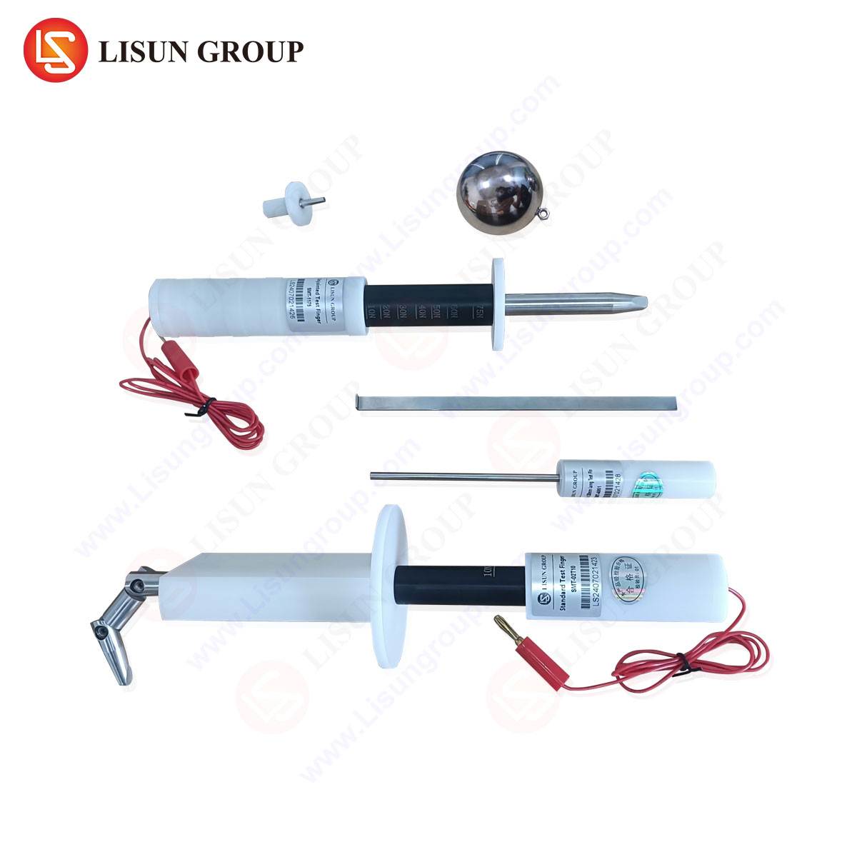
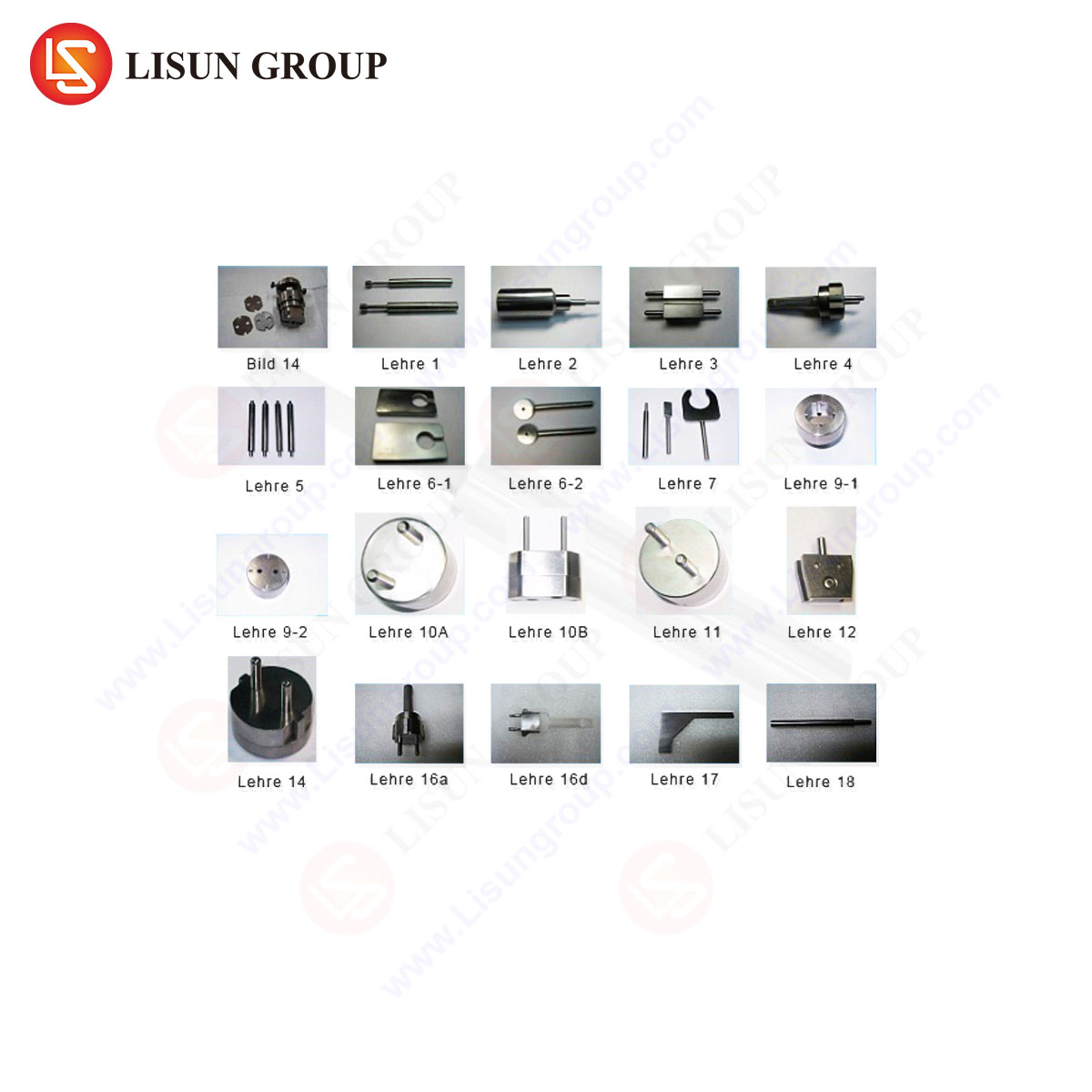
The test methodology prescribed is rigorously defined. It involves the use of a geometrically perfect, standardized test plug with pins manufactured to the dimensional limits specified in the standard. This plug is inserted and withdrawn from the socket-outlet under test a specified number of cycles, and the force is measured at a controlled, constant rate. This procedure eliminates variables related to plug geometry and operator technique, isolating the performance of the socket’s contact mechanism as the sole variable under assessment.
Instrumentation Architecture of a Modern Withdrawal Force Gauge
A contemporary VDE 0620-1 Plug Withdrawal Force Gauge, such as those engineered by LISUN, is a dedicated electromechanical system designed for metrological precision and operational robustness. The core components of this apparatus include a rigid frame structure that provides a stable base for mounting the socket-outlet under test. A precision lead screw or servo-motor system drives a crosshead, to which the standardized test plug is affixed. The critical sensing element is a high-accuracy force transducer (load cell), positioned in-line between the drive mechanism and the test plug.
The system is governed by a programmable microcontroller that manages the test sequence: initiating movement, controlling the speed of insertion and withdrawal, and sampling the analog signal from the load cell at a high frequency. This data is digitized, processed, and displayed on an integrated Human-Machine Interface (HMI), typically a touchscreen. The software algorithms are designed to identify and record the peak force encountered during the withdrawal stroke, which is reported as the test result. Advanced models incorporate features such as automatic zeroing, positional feedback for stroke length control, and data logging for traceability and quality control records.
Table 1: Representative Specifications for a LISUN LS-207 Withdrawal Force Gauge
| Parameter | Specification |
| :— | :— |
| Force Measurement Range | 0 – 50 N (or as required by standard) |
| Force Resolution | 0.01 N |
| Test Speed | Programmable, e.g., 25 mm/min, per VDE 0620-1 |
| Drive Mechanism | Servo-motor with ball screw |
| Data Output | Peak Hold, Real-time curve display |
| Control Interface | 7-inch Touchscreen HMI |
| Compliance | VDE 0620-1, GB 2099.1, and other relevant standards |
Operational Protocol for Conformity Assessment
The execution of a withdrawal force test is a systematic procedure. The socket-outlet is securely fastened to the test fixture in its intended orientation of use. The appropriate standardized test plug, whose pin dimensions are certified to be within the gauge tolerances of the standard, is attached to the gauge’s force sensor. The test program is initiated, whereby the gauge automatically inserts the plug into the socket to a predefined depth. Following a brief dwell time to allow for settling, the withdrawal cycle commences at the constant speed mandated by the standard.
As the plug is withdrawn, the force transducer continuously monitors the tensile load. The software captures the maximum force value before the plug disengages completely. This process is often repeated multiple times across different rotational orientations of the plug (e.g., 0°, 90°, 180°, 270°) to account for potential asymmetries in the socket’s contact tube alignment and spring force. The results for each orientation and the calculated average are then compared against the minimum and maximum thresholds set forth in VDE 0620-1 to determine a pass or fail outcome.
The Critical Role in Product Development and Quality Assurance
For manufacturers of plugs and socket-outlets, the withdrawal force gauge is an indispensable tool that bridges the gap between design and compliance. During the R&D phase, engineers utilize the gauge to iteratively test and refine the design of contact tubes—adjusting material thickness, heat treatment processes, and geometric form—to achieve a force value that is both compliant and provides a satisfactory user feel. In a production environment, the gauge serves as a key instrument for Statistical Process Control (SPC). By performing periodic sampling tests on production lines, manufacturers can detect drift in their stamping, forming, or heat treatment processes before non-conforming products are mass-produced.
Certification laboratories and third-party test houses, such as those affiliated with VDE, TÜV, or UL, rely on these gauges as reference equipment for type testing and product certification. The calibration and measurement uncertainty of the gauge used in these facilities are of paramount importance, as their test reports form the basis for granting market access. The data generated provides objective, quantitative evidence of conformity to the safety requirements of the standard.
Comparative Analysis of Gauge Performance Characteristics
When evaluating different withdrawal force gauges, several performance characteristics distinguish basic models from advanced, laboratory-grade instruments. The fundamental differentiator is the accuracy and long-term stability of the force measurement system. A high-precision load cell with minimal creep and hysteresis, coupled with a high-resolution analog-to-digital converter, is essential for reliable data. The drive system’s performance is equally critical; a servo-motor with a ball screw provides smoother, more consistent, and more accurate speed control compared to less sophisticated actuator systems, which reduces measurement variance.
The sophistication of the software and user interface represents another significant differentiator. Advanced systems, like those from LISUN, offer programmable test sequences, storage of multiple test standards, real-time graphical display of the force vs. displacement curve, and direct data export capabilities. The ability to view the entire force curve, rather than just a peak value, provides invaluable diagnostic information. For example, a jagged or irregular withdrawal curve may indicate binding, poor surface finish on the pins or contacts, or inconsistent spring force, allowing engineers to diagnose production issues that a simple peak reading would miss.
LISUN Gauges for Plugs and Sockets: A Synthesis of Precision and Durability
LISUN’s range of gauges for plugs and sockets, including the model LS-207 designed for VDE 0620-1 compliance, embodies an engineering philosophy focused on metrological integrity and user-centric operation. The instruments are constructed with a rigid, vibration-dampening frame to ensure that the measured force is purely axial and not influenced by frame deflection. The integrated servo-motor and ball screw drive guarantee that the test speed remains constant throughout the stroke, a non-negotiable requirement for reproducible results as per the standard.
The competitive advantage of the LISUN system lies in its holistic design. The high-resolution load cell is calibrated against traceable standards, providing a low measurement uncertainty that is critical for certification testing. The intuitive touchscreen interface allows for rapid configuration and operation, while the built-in data management system facilitates compliance with quality standards like ISO/IEC 17025 for testing laboratories. Furthermore, LISUN gauges are often designed with a modular approach, allowing a single test station to be configured with different fixtures and test plugs to cover a wide range of international standards beyond VDE 0620-1, such as BS 1363, AS/NZS 3112, and NEMA configurations, providing a versatile solution for global manufacturers.
Interpreting Force-Displacement Curves for Failure Analysis
The raw data from a withdrawal force test, when presented as a force-displacement curve, transforms the gauge from a simple pass/fail tool into a powerful diagnostic instrument. A typical successful test curve shows a gradual increase in force as the plug is withdrawn, reaching a distinct peak just before sudden release. Deviations from this ideal profile are indicative of specific failure modes.
A curve with multiple peaks or significant oscillation suggests inconsistent friction, potentially due to contamination, pitting on the contact surfaces, or a misaligned contact tube that is causing the plug pin to “stick-slip” during withdrawal. A withdrawal force that is consistently below the minimum threshold across all test orientations points to a systemic issue of insufficient contact normal force, likely stemming from incorrect contact tube geometry, sub-optimal spring temper, or excessive wear. Conversely, a force that exceeds the maximum limit indicates an over-specification of the contact tube’s spring force or poor surface finish leading to a high coefficient of friction. This analytical capability allows quality engineers to move beyond mere compliance checking and into proactive process improvement.
Ensuring Metrological Traceability and Calibration
The legal and technical validity of withdrawal force measurements hinges on metrological traceability. The force gauge must be part of a calibration chain that is linked to national or international measurement standards. This is typically achieved through periodic calibration of the instrument’s load cell using certified dead weights or a reference-grade force calibration machine. The calibration certificate should report the measurement uncertainty of the gauge under actual test conditions.
For a testing laboratory, establishing a rigorous calibration schedule is mandatory. The interval for recalibration is determined by the frequency of use, the required measurement uncertainty, and the stability of the instrument over time. A well-maintained and regularly calibrated LISUN gauge ensures that the data generated is not only precise but also accurate and legally defensible in the context of product certification and liability.
Frequently Asked Questions (FAQ)
Q1: How frequently should a VDE 0620-1 withdrawal force gauge be calibrated?
A1: The calibration interval depends on usage intensity, the criticality of the measurements, and the manufacturer’s recommendations. For high-volume production testing or certification labs, an annual calibration is typical. Laboratories accredited to ISO/IEC 17025 must define and justify their calibration intervals based on a demonstrated history of the instrument’s stability.
Q2: Can a single gauge be used to test different plug and socket standards?
A2: Yes, provided the gauge is designed with a modular fixture system. Manufacturers like LISUN offer universal frames where the socket mounting plates and standardized test plugs can be swapped out. The software can also be pre-loaded with test parameters for various standards (e.g., BS 1363, AS/NZS 3112), making it a versatile multi-standard test station.
Q3: What is the significance of testing the withdrawal force at multiple plug orientations?
A3: Testing at 0°, 90°, 180°, and 270° rotations accounts for potential anisotropies in the socket. Manufacturing variances can cause the spring force of the contact tubes to vary slightly with direction. Testing at multiple orientations ensures that the socket provides a secure connection regardless of how the plug is inserted, providing a comprehensive assessment of its mechanical quality.
Q4: If a socket fails the withdrawal force test, what are the most likely corrective actions?
A4: Corrective actions are targeted at the socket’s contact tubes. For low withdrawal force, the contact geometry may need to be adjusted to increase normal force, or the heat treatment process may require review to ensure proper spring temper. For excessively high force, polishing the contact surfaces to reduce friction or slightly relaxing the contact geometry may be necessary. The root cause is often identified by analyzing the specific shape of the force-displacement curve.