


Fundamentals of Walk-in Thermal Chamber Design and Operation
Walk-in thermal chambers represent a critical class of environmental test equipment engineered to subject large-scale products, assembled systems, and bulk components to precisely controlled temperature and humidity conditions. Unlike benchtop or reach-in chambers, their defining characteristic is their physical scale, allowing human operators to enter the test space to configure, monitor, or adjust the unit under test (UUT) during conditioning. This capability is indispensable for evaluating products that are too large for conventional chambers, require complex in-situ monitoring, or need to be tested in their operational configuration. The operational principle hinges on creating a homogeneous and stable environment within a thermally insulated enclosure. A refrigeration system, typically a cascade or multi-stage mechanical compression system, provides cooling, while electric heating elements provide heating. For humidity conditioning, a steam generator or atomizing system introduces moisture, and a dehumidification system, often integrated with the refrigeration circuit, removes it. The continuous circulation of conditioned air, driven by high-capacity blowers, ensures spatial uniformity and temporal stability, which are paramount for generating reliable and repeatable test data.
Architectural Considerations for Large-Volume Environmental Simulation
The architectural design of a walk-in chamber is a complex undertaking that balances performance specifications with structural integrity and operational practicality. The enclosure itself is typically constructed from modular panels featuring a core of high-density polyurethane or fiberglass insulation sandwiched between durable interior and exterior skins, often stainless steel or coated steel. This modular approach allows for customization of the test space dimensions to accommodate specific UUT requirements. A critical design focus is the mitigation of thermal bridging—paths of high thermal conductivity through the insulation—which can lead to localized condensation and temperature non-uniformities. The chamber door is a particularly sensitive component, requiring robust sealing mechanisms, often involving multiple gaskets and cam-lock systems, to maintain environmental integrity. The air handling system must be meticulously engineered to manage the large volume of air; this involves strategic placement of supply and return ducts, along with diffusers, to prevent stagnant zones and ensure that every point within the workspace conforms to the setpoint parameters. The choice of sensors for temperature and humidity, typically platinum resistance thermometers (PRTs) and capacitive polymer sensors respectively, and their strategic placement, is fundamental to achieving accurate control and validation.
Integrating the GDJS-015B Temperature Humidity Test Chamber for Sector-Specific Validation
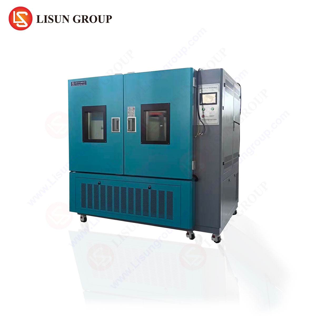
Within the broader category of walk-in chambers, specific models are designed to meet exacting standards for combined temperature and humidity testing. The LISUN GDJS-015B Temperature Humidity Test Chamber is engineered for such applications, providing a controlled environment to assess product reliability under climatic stress. Its operational range, typically spanning from -70°C to +150°C with a humidity range of 20% to 98% RH, allows it to simulate a vast spectrum of global environmental conditions, from arctic cold to tropical heat and humidity.
The testing principle involves subjecting the UUT to defined temperature and humidity profiles, which may include steady-state soaks, cyclic variations, and thermal shock transitions. For instance, in the automotive electronics sector, a complete infotainment system or an engine control unit (ECU) can be placed inside the chamber to undergo a drive cycle simulation, where temperature and humidity are cycled to mimic daily vehicle operation and prolonged exposure to high under-hood temperatures coupled with high humidity. The chamber’s control system precisely executes these profiles, while data acquisition systems can monitor the UUT’s performance parameters in real-time.
Specifications and Competitive Advantages of the GDJS-015B:
- Temperature Range: -70°C to +150°C
- Humidity Range: 20% to 98% RH
- Heating Rate: 3°C/min (average across a defined range)
- Cooling Rate: 1°C/min (average across a defined range)
- Uniformity: ≤±2.0°C (temperature), ≤±3.0% RH (humidity)
A key competitive advantage lies in its thermal stability and uniformity. The use of a balanced refrigeration circuit and a precisely engineered air circulation system ensures that the UUT, regardless of its position within the workspace, experiences the same environmental conditions. This is critical for testing compliance with international standards such as IEC 60068-2-1 (cold), IEC 60068-2-2 (dry heat), and IEC 60068-2-30 (damp heat). For example, a telecommunications equipment manufacturer validating a 5G base station unit would require this level of uniformity to ensure that performance degradation or failure modes are a result of component weakness, not test chamber artifacts.
Application in Electrical and Electronic Component Reliability Testing
The reliability of electrical and electronic components forms the bedrock of modern industrial and consumer products. Walk-in chambers like the GDJS-015B are instrumental in accelerating failure mechanisms to identify design flaws and manufacturing defects. For electrical components such as contactors, relays, and circuit breakers, cyclic humidity testing can induce surface insulation resistance (SIR) degradation, leading to dendritic growth and short circuits. By exposing these components to 85°C and 85% relative humidity for hundreds of hours, engineers can rapidly assess their longevity and robustness.
In the lighting fixtures industry, LED drivers and complete luminaire assemblies are tested for their ability to withstand thermal cycling and damp heat. A large, commercial-grade LED fixture can be powered on and operated inside the chamber while being subjected to temperature cycles from -40°C to +85°C. This test reveals failures related to solder joint fatigue, thermal expansion mismatch between materials, and condensation ingress that could lead to driver failure or optical degradation. The walk-in configuration allows for the fixture to be installed in a manner representative of its end-use application, providing highly relevant lifecycle data.
Validating Automotive Electronics Under Climatic Duress
Automotive electronics are among the most demanding applications for environmental testing. Components must operate flawlessly across a global range of climates, from desert heat to frigid cold, and while exposed to high levels of humidity and condensation. A walk-in thermal chamber is essential for testing large sub-systems like an entire automotive head unit, a battery management system (BMS) for an electric vehicle, or a Advanced Driver-Assistance Systems (ADAS) sensor cluster.
Using a chamber like the GDJS-015B, manufacturers can perform tests that simulate the life cycle of a vehicle. This includes thermal shock tests, where a component is rapidly transitioned between extreme high and low temperatures to test the integrity of materials and solder joints. Furthermore, damp heat testing is critical for evaluating the effectiveness of conformal coatings and seals against humidity-induced corrosion. The ability for engineers to enter the chamber to connect data loggers, power supplies, and diagnostic equipment to the UUT while it is under test is a significant operational advantage, reducing test cycle times and increasing the fidelity of the data collected.
Compliance and Standards Adherence in Medical Device Manufacturing
The medical device industry operates under a stringent regulatory framework where product reliability is directly linked to patient safety. Walk-in thermal chambers are used extensively for qualification and validation testing of medical devices, ensuring they meet standards such as ISO 13485 and specific pharmacopoeial requirements for storage conditions. Devices ranging from large imaging machines like MRI and CT scanners to incubators and automated diagnostic analyzers must be validated for performance under various environmental conditions encountered during shipping, storage, and operation.
For instance, a diagnostic analyzer may be tested for its ability to maintain precise temperature control for its reagent storage and reaction chambers while the ambient chamber temperature is cycled. Any deviation could lead to inaccurate test results. The data logging capabilities of a chamber like the GDJS-015B are crucial here, providing a validated and auditable trail of the environmental conditions the device was subjected to, which is a mandatory requirement for regulatory submissions to bodies like the U.S. FDA or the European Medicines Agency.
Operational Protocols and Safety Interlocks for Large-Scale Testing
Operating a walk-in thermal chamber involves a set of rigorous protocols to ensure both the integrity of the test and the safety of personnel. Safety is paramount, given the extreme temperatures and the confined space nature of the chamber. A comprehensive suite of safety interlocks is non-negotiable. These typically include:
- Door Safety Interlocks: Halt the test and initiate a safe shutdown or hold condition when the door is opened, preventing a sudden and dangerous exchange of hot/cold air with the laboratory environment.
- Emergency Stop Buttons: Located both inside and outside the chamber for immediate system shutdown.
- Overtemperature Protection: A independent, redundant safety thermostat that bypasses the main controller to cut power to the heaters in the event of a controller failure.
- Gas Monitoring: For chambers that reach very low temperatures, oxygen deficiency monitors are essential to ensure operator safety when entering, as liquid nitrogen or CO2 cooling systems can displace breathable air.
Standard Operational Procedures (SOPs) dictate the process for loading the UUT, establishing sensor connections, securing cabling through specialized ports, and initiating the test profile. A critical pre-test step is often a “soak” period, where the UUT is stabilized at a standard ambient condition before the test profile begins, ensuring all tests start from a known baseline.
Data Acquisition and System Integration Capabilities
The value of environmental testing is fully realized only when correlated with the performance data of the UUT. Modern walk-in chambers are not merely environmental conditioners; they are integrated data hubs. They feature sophisticated programmable logic controllers (PLCs) or PC-based systems that not only manage the chamber’s climate but also communicate with external data acquisition (DAQ) systems.
Ethernet, RS-232/485, and GPIB interfaces are standard, allowing the chamber controller to be integrated into a broader test automation framework. This enables synchronized operation where the chamber’s environmental profile can be triggered by, or can trigger, the operational cycles of the UUT. For example, when testing an industrial control system, the test sequence might involve ramping the chamber to 60°C and 95% RH and then initiating a diagnostic software suite on the UUT. The UUT’s pass/fail status, along with critical parameters like processor temperature, voltage rails, and communication error rates, are logged alongside the chamber’s temperature and humidity data. This creates a comprehensive dataset for root cause analysis, showing precisely which environmental condition precipitated a failure.
Future Trends in Large-Volume Environmental Simulation
The evolution of walk-in thermal chambers is closely tied to advancements in the industries they serve. A prominent trend is the increasing demand for multi-stress testing, where temperature and humidity are combined with other environmental factors such as vibration (combined environmental testing), altitude (low pressure), and solar radiation. This provides a more accurate simulation of real-world operating conditions, particularly for aerospace and automotive applications.
Another significant trend is the move towards greater energy efficiency. The substantial energy consumption of large chambers is a major operational cost. Innovations in compressor design, the use of variable frequency drives (VFDs) on motors, and more efficient heat exchangers are being implemented to reduce the carbon footprint and total cost of ownership. Furthermore, the integration of Industrial Internet of Things (IIoT) capabilities is becoming more common, enabling predictive maintenance by monitoring component wear (e.g., compressor valve health, refrigerant pressure trends) and facilitating remote monitoring and control of tests from anywhere in the world, thereby optimizing laboratory resource utilization.
Frequently Asked Questions (FAQ)
Q1: What is the primary distinction between a walk-in thermal chamber and a thermal shock chamber like the HLST-500D?
A walk-in chamber is designed for testing large items or bulk components under steady-state or ramping temperature and humidity profiles, often with operator access during testing. In contrast, a thermal shock chamber, such as the HLST-500D, is specialized for rapidly transferring a product between two or three extreme temperature zones (e.g., -55°C to +125°C) to test the robustness of materials and solder joints against rapid temperature change stresses. The HLST-500D is typically a smaller, dual-zone cabinet not designed for operator entry.
Q2: How is temperature uniformity validated across the entire workspace of a large walk-in chamber?
Uniformity is validated through a process called mapping. Multiple calibrated sensors are placed at various locations within the empty workspace, including geometric corners and the center, as defined by standards such as IEC 60068-3-5. The chamber is then stabilized at setpoints (e.g., -40°C, +25°C, +85°C) and the temperature readings from all sensors are recorded. The uniformity specification is derived from the maximum deviation between any two sensors at each setpoint, ensuring the entire volume meets the required performance.
Q3: What considerations are necessary for running powered tests on devices inside the chamber?
Powered testing requires careful planning. Cables for power and signal must be routed through specially designed feed-through ports that maintain the chamber’s thermal and humidity integrity. The power dissipation of the UUT itself must be considered, as it acts as an additional heat source and can challenge the chamber’s ability to maintain low-temperature setpoints. The chamber’s refrigeration capacity must be rated to handle both the chamber’s thermal load and the UUT’s heat output.
Q4: Can a walk-in chamber be used for burn-in testing of electronic assemblies?
Yes, walk-in chambers are frequently used for high-volume burn-in testing. In this application, electronic boards or complete products are powered on and operated at an elevated temperature (e.g., 40-60°C) for an extended period (e.g., 24-168 hours). This process accelerates early-life failures (infant mortality), weeding out defective units before they are shipped to customers. The large volume of a walk-in chamber allows for the simultaneous burn-in of hundreds or thousands of units, making it a cost-effective solution for high-volume manufacturers.