


A Technical Examination of SB1276A Figure 124.1 Compliance: Methodologies, Instrumentation, and Industry Implications
Introduction to SB1276A and the Imperative of Mechanical Safety
The regulatory landscape governing the safety of plugs, socket-outlets, and associated interconnecting devices is both complex and critical. Among the myriad of standards, California’s SB1276A, and specifically the mechanical integrity test delineated in its Figure 124.1, represents a pivotal compliance checkpoint for manufacturers and testing laboratories globally. This standard, often adopted or referenced beyond its jurisdictional origin due to its rigor, mandates a precise evaluation of a plug’s resistance to blade deformation under mechanical stress. The underlying principle is not merely one of component durability, but of fundamental electrical safety. A plug blade that deforms excessively under insertion or withdrawal forces can compromise electrical contact within the socket, leading to increased contact resistance, localized heating, and ultimately, a heightened risk of fire initiation or electrical failure. Consequently, compliance with SB1276A Figure 124.1 is not a voluntary design goal but a non-negotiable prerequisite for market access and consumer safety assurance. This article provides a detailed technical dissection of the compliance testing procedure, the specialized instrumentation required for its execution, and the integral role of precision measurement tools such as the LISUN Gauges for Plugs and Sockets in ensuring accurate, repeatable, and standards-aligned verification.
Deconstructing the SB1276A Figure 124.1 Test Procedure
The test prescribed in SB1276A Figure 124.1 is a controlled simulation of the mechanical forces exerted on a plug’s current-carrying blades during a misaligned insertion attempt. The procedure is methodical and prescriptive. The specimen plug is securely mounted in a fixed position. A standardized test apparatus, which incorporates a simulated socket contact of specified geometry and material, is then aligned to apply a force perpendicular to the longitudinal axis of the plug blade under test. The critical parameter is the application of a defined force—typically quantified in Newtons (N)—to the blade at a point 3.2 millimeters from its tip. This force is maintained for a stipulated duration, often one minute, to assess both immediate and time-influenced deformation.
Following the force application and subsequent release, the plug is not merely inspected visually. It must be subjected to a quantitative metrological assessment. The permanent set, or deformation, of the blade is measured with high precision. The standard explicitly defines the maximum permissible deformation, often on the order of 0.8 millimeters or less, depending on the blade type and applicable national variant of the standard. This quantitative limit underscores the necessity for measurement resolution exceeding the tolerance itself; gauges must reliably discriminate deviations of 0.01mm or finer to provide a definitive pass/fail judgment. The entire process must be repeatable across multiple samples from a production lot to validate manufacturing consistency, necessitating instrumentation that eliminates operator subjectivity.
Metrological Foundations: The Critical Role of Specialized Plug and Socket Gauges
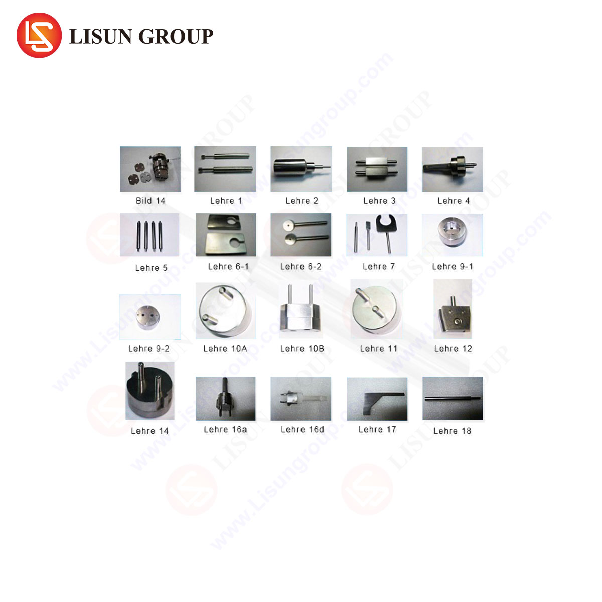
The transition from a procedural description to a legally defensible compliance statement hinges entirely on metrological accuracy. Standard calipers or micrometers, while useful for general inspection, lack the specific geometry and application methodology required by SB1276A. This is the domain of specialized plug and socket gauges. These instruments are not general-purpose measuring devices; they are purpose-engineered artifacts that physically embody the dimensional and geometric requirements of the standard.
A compliant gauge system for this application typically consists of two primary components: a “Go/No-Go” functional gauge and a quantitative deformation measurement gauge. The functional gauge quickly assesses whether a deformed plug can still properly engage with a standard socket-outlet, serving as a preliminary safety check. However, for SB1276A Figure 124.1, the quantitative measurement gauge is paramount. This device is designed to precisely locate the measurement datum on the plug blade (the point 3.2mm from the tip) and provide a direct, highly accurate reading of the blade’s offset from its original, undeflected plane. The gauge must feature a calibrated dial indicator or digital readout with appropriate resolution, a rigid reference structure that contacts the non-deformed portions of the plug body, and a probe that contacts the blade at the exact specified point. Any deviation in the gauge’s own geometry or calibration invalidates the entire test series, potentially leading to non-compliant products entering the market or unnecessary rejection of conforming components.
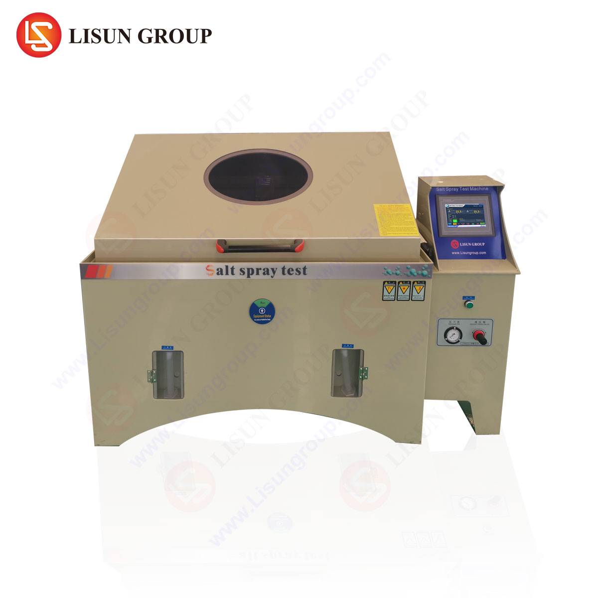
Instrumentation in Practice: The LISUN Gauges for Plugs and Sockets System
To illustrate the application of these metrological principles, we examine the LISUN Gauges for Plugs and Sockets, a system engineered explicitly for compliance testing to standards including SB1276A, UL 498, IEC 60884, and AS/NZS 3112. This system exemplifies the integration of design specificity, material science, and calibration rigor required for authoritative testing.
The LISUN system addresses the SB1276A Figure 124.1 test through a dedicated deformation measurement fixture. Its design incorporates a hardened steel reference anvil that securely registers against the plug’s insulating body and the base of the blade not subject to the test force, ensuring the measurement axis is orthogonal to the direction of applied force. A precision-ground contact probe, positioned via a micrometer stage or a fixed, certified distance block, engages the blade at the critical 3.2mm point. Displacement is transmitted to a calibrated digital indicator with a resolution of 0.001mm (1 micron), far exceeding the typical deformation tolerance. The fixture is constructed from materials with low thermal expansion coefficients to ensure dimensional stability across laboratory environmental fluctuations.
Specifications of such a system are telling of its capability. Measurement ranges are tailored to specific plug configurations (e.g., NEMA 1-15, NEMA 5-15, AS/NZS Type I). The system’s accuracy is traceable to national metrology institutes, with documented calibration certificates forming an essential part of the quality audit trail. Repeatability and reproducibility (Gauge R&R) studies are crucial, and well-designed systems demonstrate minimal variation between operators and repeated measurements on the same sample. For high-throughput quality control laboratories, LISUN and similar systems may offer automated data logging, directly recording deformation values against sample IDs for statistical process control (SPC) analysis and automated report generation, thereby reducing human error in transcription.
Industry Applications and Validation Workflows
The utility of precise gauging extends beyond simple pass/fail determination at the end of a production line. It is integral to a holistic product development and validation workflow. During the design phase, engineers use these gauges to iteratively test prototype plug molds, assessing different blade alloys (e.g., brass, phosphor bronze), thicknesses, and heat-treatment processes. By obtaining precise deformation data, they can optimize material selection and geometry to meet the safety margin with cost-effective manufacturing in mind.
In the production environment, the gauges serve a dual purpose. First, they are used for mandatory type-testing of finished products, where a statistically significant sample size from a production batch is subjected to the full SB1276A test sequence. Second, they are employed for in-process control. A simplified gauge check on blade thickness and hardness, or a periodic full deformation test on sampled components, can provide early warning of tooling wear in the injection molding or stamping processes before an entire production run falls out of specification. For certification bodies and third-party testing laboratories, the use of accredited, traceable gauge systems like the LISUN suite is a fundamental requirement for issuing test reports that are recognized by regulatory authorities and sourcing departments of major retailers and OEMs.
Comparative Analysis: Advantages of Integrated, Purpose-Built Gauge Systems
The competitive advantage of a dedicated system over improvised measurement setups is multi-faceted. The primary benefit is standard compliance assurance. The fixture geometry is machined to the exact contours specified in the standard’s referenced diagrams, removing interpretation and setup error. Metrological traceability, provided through a full calibration dossier, is essential for audit compliance and legal defensibility. Operational efficiency is significantly enhanced; a technician can perform a measurement in seconds with a dedicated gauge, compared to minutes of careful alignment with universal tools, directly impacting laboratory throughput and cost-per-test.
Furthermore, measurement uncertainty is minimized. A purpose-built fixture controls variables such as probe angle, reference point location, and clamping force on the plug, which are difficult to control consistently with calipers. This leads to superior repeatability and reproducibility (R&R), a key metric in measurement system analysis (MSA) that is scrutinized during laboratory accreditation audits to ISO/IEC 17025. Finally, ergonomic design reduces operator fatigue and the potential for repetitive strain, while integrated data output capabilities streamline quality documentation and facilitate trend analysis for predictive maintenance of manufacturing equipment.
Conclusion: The Confluence of Standard, Test, and Measurement
SB1276A Figure 124.1 compliance testing embodies the critical link between a written safety standard and tangible product safety. It transforms a qualitative concern—plug blade strength—into a quantitative, verifiable metric. The integrity of this transformation is wholly dependent on the precision, accuracy, and standardization of the measurement instruments employed. As global supply chains demand uniform safety performance and regulatory harmonization progresses, the role of certified, reliable, and efficient gauge systems becomes increasingly central. They are not merely tools for inspection but are foundational components of a robust product safety ecosystem, ensuring that the mechanical interface between plug and socket, a connection made countless times daily, remains predictably safe under foreseeable conditions of use. The continued evolution of these gauging systems, integrating higher levels of automation, data connectivity, and intelligent analysis, will further solidify their position as indispensable assets in the manufacture and certification of electrical wiring accessories.
FAQ Section
Q1: Can a universal digital caliper be used for SB1276A Figure 124.1 deformation measurement instead of a dedicated gauge?
A: While a caliper can measure distance, it is not suitable for compliant testing. The standard requires measurement at a specific point (3.2mm from the blade tip) relative to the plug body’s reference planes. A caliper cannot reliably and repeatably establish these datums simultaneously, introducing significant measurement uncertainty and operator dependency. Dedicated gauges are designed to enforce the correct measurement geometry, ensuring results are aligned with the standard’s intent.
Q2: How often should a plug and socket deformation gauge be calibrated?
A: Calibration intervals are determined by the laboratory’s quality procedures, often aligned with ISO/IEC 17025 requirements, usage frequency, and historical stability data. A typical interval for active laboratory use is 12 months. However, if the gauge is subjected to shock, damage, or its annual verification check indicates drift, immediate recalibration is required. All calibrations must be traceable to national measurement standards.
Q3: Does the LISUN gauge system accommodate different international plug types?
A: Yes, comprehensive systems are modular. They utilize a common base measurement frame with interchangeable fixture inserts and probe assemblies that are specifically configured for different plug standards—such as NEMA (North America), BS 1363 (UK), CEE 7/7 (Schuko), AS/NZS 3112 (Australia/New Zealand), and others. Each insert is manufactured to the dimensional specifications of the relevant standard.
Q4: What is the consequence of a plug blade deforming beyond the limit in the SB1276A test?
A: A failure indicates the plug does not possess sufficient mechanical strength to withstand normal (or slightly misaligned) insertion forces without permanent deformation. This can lead to poor electrical contact in the socket, resulting in arcing, overheating, and a potential fire hazard. A failing result typically necessitates a redesign of the plug blade (material, thickness, alloy treatment) and requires full re-testing of the modified product before it can be deemed compliant.
Q5: Can these gauges be used for in-process quality control on the manufacturing floor?
A: Absolutely. While laboratory-grade systems offer the highest precision for certification testing, robust, simplified versions of these gauges are deployed on production lines for statistical process control (SPC). They allow for rapid checks of blade dimensional integrity, enabling operators to detect tooling wear or material inconsistencies in real-time, preventing the manufacture of non-conforming products.