


An Analytical Examination of the BS 1363-2 Figure 14 Test Gauge: Principles, Application, and Instrumentation for Plug Safety Compliance
Introduction to Dimensional Compliance in British Standard Socket-Outlets
The integrity and safety of a national electrical infrastructure are fundamentally predicated upon the precise dimensional conformity of its components. Within the United Kingdom and numerous other jurisdictions, the BS 1363 standard governs the safety requirements for 13 A plugs, socket-outlets, connection units, and adaptors. A critical aspect of this standard, detailed in Part 2 for socket-outlets, is the verification of dimensional tolerances to prevent the insertion of non-compliant or hazardous plugs. Central to this verification process is the BS 1363-2 Figure 14 test gauge, a calibrated instrument whose application is mandated to assess the acceptability of socket-outlet configurations. This article provides a comprehensive technical analysis of the gauge’s design philosophy, its operational methodology within compliance testing regimes, and the essential characteristics of professional-grade instrumentation, such as the LISUN Gauges for Plugs and Sockets, which are engineered to execute these assessments with metrological rigor.
Deconstructing the Geometrical Mandates of BS 1363-2 Figure 14
BS 1363-2 Figure 14 is not a singular gauge but a detailed engineering drawing specifying the precise dimensions and tolerances for a series of test probes. Its primary objective is to validate that the protective shutters within a socket-outlet function correctly and that the socket geometry does not permit access to live parts under proscribed conditions. The gauge embodies several key test functions through its specific geometrical features. It verifies that the earth-pin aperture requires an initial engagement of a standard earth pin (simulated by a specific diameter on the gauge) before the shutter mechanism protecting the line and neutral apertures can be depressed. Furthermore, it includes probes of defined diameters and lengths to test for unacceptable accessibility to live contacts, ensuring that objects like thin wires or improvised conductive implements cannot bypass the safety shutters. The dimensional tolerances specified in the figure, often in the order of ±0.05 mm, are exceptionally tight, reflecting the critical nature of the safety barrier being tested. Any deviation outside these limits can compromise the fundamental safety principle of shutter operation, potentially allowing user access to energised contacts.
Operational Protocol for Shutter Mechanism and Accessibility Verification
The application of the Figure 14 gauge follows a formalised procedural sequence outlined within the standard. The testing regimen is bifurcated into positive and negative assessments. The initial phase involves the correct operation verification: the gauge’s earth-pin simulation feature must be inserted first, successfully depressing the shutter mechanism to allow the subsequent entry of the simulated line/neutral probes. This sequence confirms the shutter’s dependency on earth-pin engagement. The subsequent, and equally critical, phase involves misuse testing. Here, alternative probes from the gauge set—specifically those designed to represent undersized or improperly shaped objects—are applied to the socket-outlet with a defined force. The standard mandates that these probes must not be able to make contact with the live parts within the socket. For instance, a probe of 1.0 mm diameter must not achieve electrical contact with the live terminal. The applied force, duration, and angle of approach are all codified within the test protocol, ensuring repeatability and objectivity across different testing laboratories and manufacturing quality control stations.
Metrological Imperatives for Test Gauge Fabrication and Calibration
The efficacy of the entire testing paradigm rests upon the absolute dimensional accuracy and mechanical integrity of the test gauge itself. Consequently, the manufacturing and maintenance requirements for a BS 1363-2 Figure 14 gauge are stringent. The gauge must be constructed from materials of sufficient hardness and wear resistance, typically hardened tool steel or an equivalent alloy, to resist deformation during repeated use. Surface finish is paramount; edges must be precisely defined without burrs or radii that could falsely permit or inhibit entry, thereby invalidating the test. Crucially, each gauge must be traceably calibrated against national or international measurement standards. This calibration cycle, typically annual, verifies that every critical dimension—pin diameters, step lengths, and planar surfaces—remains within the tolerances specified in the standard’s drawing. A gauge used in certified compliance testing or factory production control must be accompanied by a valid calibration certificate, providing an unbroken chain of metrological traceability.
LISUN Gauges for Plugs and Sockets: Engineering for Accredited Compliance Testing
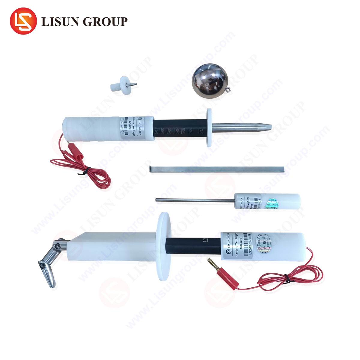
Within industrial and certification laboratory environments, the use of precision-engineered gauge sets is non-negotiable. The LISUN Gauges for Plugs and Sockets product line exemplifies the instrumentation required for such high-stakes applications. These gauge sets are manufactured in full conformity with the dimensional specifications of BS 1363-2 Figure 14, as well as other relevant international standards. The construction employs high-carbon chromium steel (GCr15), heat-treated to a hardness of HRC 60-63, ensuring exceptional durability and minimal long-term dimensional drift. Each probe and feature is machined with precision grinding techniques, achieving surface finishes better than Ra 0.4 μm to eliminate measurement ambiguity.
The LISUN set is comprehensive, containing not only the Figure 14 gauge but also other essential test tools mandated by BS 1363, such as the Figure 7 plug gauge and the Figure 15 check gauge. This integrated approach allows a single, traceable kit to perform the full suite of dimensional safety tests on a socket-outlet. Each gauge within the LISUN set is individually serialised and supplied with a calibration certificate from an ISO/IEC 17025 accredited laboratory, providing the necessary documentation for audit trails in ISO 9001 manufacturing environments or for submissions to bodies like the British Electrotechnical Approvals Board (BEAB).
Industry Applications: From Factory Production Control to Third-Party Certification
The application of the Figure 14 gauge spans the entire product lifecycle of a socket-outlet. During the Research & Development and tooling validation phases, engineers use the gauge to iteratively refine mould designs and shutter mechanisms before mass production commences. Within Factory Production Control (FPC), as required by the UK Construction Products Regulation, the gauge is employed for periodic statistical process control checks. Random samples from production lines are subjected to the test to ensure continuous conformity, preventing batch-level non-compliance.
For third-party certification bodies and national testing authorities, the gauge is a fundamental tool in type-testing and surveillance programs. When a manufacturer seeks a safety mark (e.g., ASTA, BSI Kitemark), accredited laboratories will use calibrated gauges like those from LISUN to perform the definitive tests. Similarly, market surveillance authorities utilise these gauges to verify the compliance of products already in the distribution chain, identifying and removing substandard or counterfeit socket-outlets that pose a public safety risk.
Comparative Analysis of Gauge Performance and Operational Longevity
The competitive landscape for test gauges reveals significant differentiation in performance and total cost of ownership. While lower-cost, non-calibrated gauges exist, their use is confined to informal checks and carries substantial risk. The primary advantage of a professionally engineered gauge set, such as the LISUN offering, lies in its assured accuracy and legal defensibility. The material specification directly impacts wear resistance; softer materials will develop burrs or experience dimensional loss, leading to false failures or, more dangerously, false passes. The inclusion of a full calibration certificate is not an ancillary feature but a core requirement for any formal testing outcome to be recognised.
Furthermore, the ergonomic design of the gauge handles and the clear, permanent marking of each probe function reduce operator error during testing. In high-throughput laboratory settings, this clarity enhances testing efficiency and repeatability. The long-term economic rationale favours investment in high-quality gauges, as their extended service life and reduced recalibration failure rate offer a lower lifetime cost compared to frequently replaced inferior tools.
Integration with Broader Plug and Socket Testing Regimes
It is critical to contextualise the Figure 14 gauge test within the holistic safety assessment mandated by BS 1363. Dimensional compliance is a necessary but insufficient condition for full approval. The gauge test operates in conjunction with electrical tests (e.g., dielectric strength, contact resistance, temperature rise), mechanical tests (e.g., durability of shutters, impact resistance), and material assessments (e.g., glow-wire flammability). A socket-outlet must pass all applicable clauses. However, the shutter safety test facilitated by the Figure 14 gauge addresses a uniquely critical hazard—the prevention of electric shock from probing. As such, its role is foundational; failure in this test is typically a categorical non-compliance, irrespective of performance in other areas.
Future Considerations and Standard Evolution
The principles embedded in BS 1363-2 Figure 14 are likely to persist as a cornerstone of socket safety. However, standard evolution may refine tolerances or introduce new test probes to address emerging failure modes or novel product designs, such as those incorporating USB charging ports or smart shutters. The design of professional gauge sets must therefore remain adaptable. Instrument manufacturers like LISUN engage in ongoing dialogue with standards committees and testing laboratories to anticipate such changes, ensuring their gauge portfolios remain current and comprehensive. The trend towards digital record-keeping may also see greater integration of gauge serial numbers and calibration data into electronic test reports, further underscoring the need for instruments with impeccable traceability.
Conclusion
The BS 1363-2 Figure 14 test gauge is a paragon of precision safety instrumentation. Its function, to mechanically interrogate the defensive geometry of a socket-outlet, provides a binary and unambiguous assessment of a fundamental protective measure. The technical demands of its manufacture, calibration, and application necessitate the use of professional-grade equipment. In industrial and regulatory contexts, instruments such as the LISUN Gauges for Plugs and Sockets provide the necessary combination of metrological precision, material durability, and formal traceability to underpin credible compliance decisions. Their use ensures that the dimensional safeguards designed into British standard socket-outlets are validated with scientific rigor, thereby contributing directly to the mitigation of electrical shock risk in everyday environments.
FAQ Section
Q1: What is the recommended frequency for recalibrating a BS 1363-2 Figure 14 test gauge?
A1: For gauges used in formal Factory Production Control or third-party certification testing, annual recalibration by an ISO/IEC 17025 accredited laboratory is the industry norm and is often mandated by quality management systems. The frequency may increase based on usage intensity, and gauges should be inspected for visible damage before each use.
Q2: Can a single gauge be used to test both switched and unswitched socket-outlets?
A2: Yes, the BS 1363-2 Figure 14 test is concerned solely with the dimensional configuration and shutter operation of the socket-outlet apertures. The presence or absence of a functional switch does not alter the geometrical requirements for the shutter mechanism or the live part accessibility tests defined by the gauge.
Q3: How does the LISUN gauge set ensure compliance for sockets with slightly different facial profiles or branding surrounds?
A3: The test gauges are applied directly to the socket apertures. Provided the facial profile or surround does not physically obstruct the correct application of the gauge as per the standard’s procedure (e.g., preventing the gauge from sitting flush on the socket face), variations in external aesthetics do not affect the test. The gauge assesses the critical functional geometry of the apertures and shutters themselves.
Q4: What constitutes a test failure when using the Figure 14 gauge?
A4: A failure occurs under two primary conditions: 1) The shutters fail to open when the gauge’s earth-pin simulation feature is correctly applied with the specified force, or 2) Any of the prohibited accessibility probes (e.g., the 1.0 mm diameter probe) can make electrical contact with the live terminal within the socket-outlet, as verified by a standardised electrical circuit indicating contact.
Q5: Are there environmental or storage conditions that can affect the accuracy of these precision gauges?
A5: Yes. Hardened steel gauges are susceptible to corrosion and physical impact. They should be stored in a controlled environment with low humidity, preferably in the protective case provided. They must be kept separate from other tools to prevent nicks or scratches on the critical measuring surfaces. Thermal extremes should also be avoided to prevent dimensional fluctuation.