


Advancements in Environmental Stress Screening for Battery-Powered Systems
The proliferation of battery-powered technologies across virtually every industrial and consumer sector has precipitated a paradigm shift in product validation methodologies. The performance, safety, and longevity of these systems are intrinsically linked to the electrochemical stability of their power sources, which is profoundly influenced by environmental conditions. Consequently, rigorous environmental stress screening (ESS) has transitioned from a recommended practice to a non-negotiable phase in the design, validation, and qualification lifecycle. Central to this process is the battery environmental chamber, a sophisticated apparatus designed to simulate and accelerate the effects of climatic and thermal extremes on battery cells, modules, and integrated systems.
The Electrochemical Imperative for Controlled Environmental Stress
Batteries, particularly lithium-ion chemistries, are complex electrochemical systems whose key parameters—capacity, internal impedance, cycle life, and safety thresholds—exhibit significant temperature and humidity dependence. At low temperatures, electrolyte viscosity increases and ionic conductivity decreases, leading to reduced power capability and the risk of lithium plating during charging, a primary failure mechanism. Elevated temperatures accelerate parasitic side reactions, including solid electrolyte interphase (SEI) growth and electrolyte decomposition, resulting in irreversible capacity fade and gas generation. Humidity can compromise sealing integrity, leading to internal corrosion and potential thermal runaway. Therefore, isolating and quantifying these environmental effects under controlled, reproducible conditions is not merely beneficial but essential for predictive reliability modeling and failure mode analysis.
Architectural Principles of a Modern Battery Testing Chamber
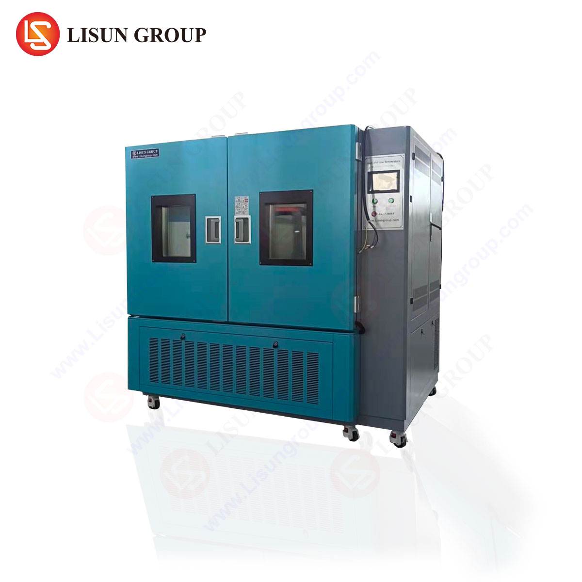
A reliable battery environmental chamber is engineered to provide precise, uniform, and stable control over temperature and humidity while integrating critical safety and monitoring functionalities for high-risk energy-dense samples. The architectural philosophy extends beyond basic climatic simulation to address the unique challenges posed by batteries. This includes robust thermal mass management to handle exothermic and endothermic reactions during charge/discharge cycles, intrinsically safe construction to contain potential thermal events, and dynamic control algorithms that can simulate real-world thermal profiles, such as those experienced by an electric vehicle battery pack during fast charging in desert heat or regenerative braking in arctic cold.
Electrical feedthroughs with appropriate current ratings and isolation are mandatory for in-situ performance testing. Furthermore, comprehensive data acquisition systems must synchronize environmental parameters (chamber temperature, sample surface temperature, humidity) with electrical performance data (voltage, current, impedance) to establish causal relationships. The chamber’s construction materials must be non-flammable and resistant to off-gassing products, while internal airflow designs must ensure spatial uniformity typically within ±0.5°C to guarantee that all samples or sample regions experience identical stress conditions, a critical factor for validating battery module balance.
The HLST-500D Thermal Shock Test Chamber: A Case Study in Extreme Transition Testing
For evaluating the resilience of batteries and their host electronics to rapid thermal transitions—a common stressor in applications like automotive, aerospace, and portable electronics—the thermal shock test chamber is indispensable. The LISUN HLST-500D exemplifies a two-zone, basket-transfer type thermal shock chamber designed to meet stringent standards such as IEC 60068-2-14 (Test N: Change of temperature) and MIL-STD-202G.
Testing Principle and Operation:
The HLST-500D operates on a dual-compartment principle. A high-temperature zone and a low-temperature zone are maintained at stable, user-defined extremes. A mechanically driven basket, holding the test specimens, transfers rapidly between zones. The transition time is a critical performance metric; the HLST-500D achieves a transfer time of less than 10 seconds, ensuring the specimen is exposed to the air temperature shock rather than a gradual ramp. This rapid transition induces mechanical stresses due to the differential coefficient of thermal expansion (CTE) of dissimilar materials within a battery pack—such as electrodes, separators, casings, and welded joints—potentially revealing latent defects like cracked welds, delamination, or seal failure.
Key Specifications:
- Temperature Range: High Temperature Zone: +60°C to +200°C; Low Temperature Zone: -10°C to -65°C (extendable to -80°C).
- Recovery Time: ≤5 minutes after specimen transfer.
- Chamber Volume: 500 liters (providing ample space for multiple battery modules or sizable electronic assemblies).
- Basket Capacity: Standard load capacity of 30kg, sufficient for dense battery packs.
- Control System: Programmable controller allowing for pre-set cycles of dwell times and transfers, enabling fully automated, long-duration test sequences.
Industry-Specific Applications and Validation Protocols
The application of chambers like the HLST-500D spans industries where reliability under thermal shock is paramount.
- Automotive Electronics & Electric Vehicles: Battery management systems (BMS), traction battery modules, and onboard chargers are subjected to tests simulating a vehicle moving from extreme winter cold into a heated garage, or a battery pack undergoing fast charging after cold-soaking. Tests validate solder joint integrity on PCBAs, connector stability, and the mechanical integrity of cell-to-cell connections.
- Aerospace and Aviation Components: Avionics batteries and power systems for satellites must endure rapid changes during ascent/descent or when moving in and out of planetary shadow. Thermal shock testing reveals workmanship flaws that could lead to mission-critical failures.
- Telecommunications Equipment: Backup battery systems (e.g., for 5G infrastructure) in outdoor cabinets experience daily and seasonal cycles. Testing ensures that prolonged exposure to these cycles does not cause interconnect failures within battery strings.
- Medical Devices: Implantable device batteries and portable diagnostic equipment must remain functional after transportation or storage in non-conditioned environments. Shock testing validates hermetic seals and internal connections.
- Lighting Fixtures (e.g., EV Headlights, Industrial LED): Integrated battery-backed or driver electronics within lighting assemblies are tested for resilience to sudden environmental changes, preventing condensation ingress or solder fatigue.
Integrating Shock Testing into a Comprehensive Reliability Strategy
While thermal shock testing is a potent tool for uncovering gross workmanship and design flaws, it is most effective when integrated into a broader test regimen. A typical battery validation pyramid might include:
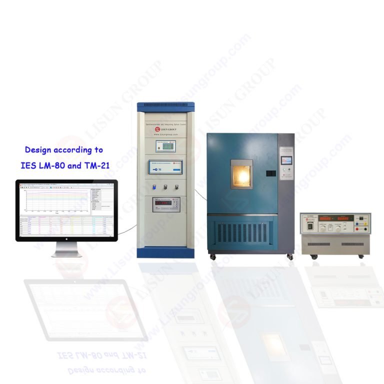
- Characterization: Using temperature/humidity chambers (like the GDJS series) for long-term cycle life testing at constant or slowly cycled conditions to model degradation.
- Stress Screening: Employing thermal shock (HLST-500D) for accelerated mechanical stress and defect precipitation.
- Abuse Testing: Conducting separate tests for overcharge, short circuit, and crush in dedicated safe-test facilities.
Data correlation across these tests allows engineers to differentiate between failure modes originating from gradual electrochemical decay versus sudden mechanical stress.
Safety Considerations and Chamber Design Implications
Testing energy-dense batteries introduces unique hazards. A chamber like the HLST-500D must incorporate safety features beyond standard climatic chambers. These include:
- Explosion-Relief Venting: Strategically designed pressure-release mechanisms to safely vent gases in the event of cell venting or thermal runaway.
- Inert Atmosphere Option: The ability to purge the test zone with nitrogen or argon to mitigate fire risk, particularly during testing of damaged or prototype cells.
- Fire Suppression Ports: Pre-installed ports for integration with external fire suppression systems.
- Robust Internal Construction: Use of stainless steel and other non-reactive, high-strength materials that can withstand minor internal events and are easy to clean from electrolyte residues.
Standards Compliance and Data Integrity
Reliable testing is synonymous with traceable and standards-compliant processes. The HLST-500D facilitates compliance with key industry standards:
- IEC 60068-2-14: The foundational international standard for change-of-temperature tests.
- MIL-STD-202G / 810G: U.S. military standards defining environmental test methods for electronic components and equipment.
- ISO 16750-4: Automotive standard for environmental conditions and testing for electrical and electronic equipment, specifically addressing thermal shock.
- GB/T 2423.22: The Chinese national standard equivalent to IEC 60068-2-14.
Adherence to these standards ensures not only the mechanical performance of the chamber but also the validity of the test profiles executed within it, which is critical for regulatory submissions and customer acceptance.
Conclusion: Enabling the Next Generation of Energy Storage Reliability
As battery technology advances towards higher energy densities, faster charging rates, and broader operational envelopes, the role of precision environmental testing becomes increasingly critical. Equipment such as the HLST-500D Thermal Shock Test Chamber provides the necessary controlled extreme environment to de-risk product development, accelerate time-to-market, and ultimately deliver the reliability that modern industries demand. By enabling engineers to precipitate and analyze failures in the laboratory, these chambers form a cornerstone of the proactive reliability engineering that underpins safe and durable battery-powered systems across the global economy.
FAQ Section
Q1: What is the primary difference between a thermal shock test and a temperature cycling test?
A thermal shock test subjects the specimen to extreme, rapid transitions between two set temperature extremes, with minimal transition time (seconds). The goal is to induce mechanical stress from rapid contraction/expansion. A temperature cycling test typically involves slower, controlled ramps between extremes, focusing more on the cumulative effects of prolonged exposure to high and low temperatures and the fatigue induced by slower cycles. They uncover different classes of potential failures.
Q2: Can the HLST-500D be used to test batteries while they are actively charging and discharging?
Yes, but this requires careful configuration. The chamber must be equipped with appropriately rated electrical feedthroughs to connect the batteries to an external cycler or load. All safety protocols must be rigorously followed, as this constitutes a more hazardous “live testing” scenario. The chamber’s safety features, such as explosion venting, become particularly crucial in this use case.
Q3: How is temperature uniformity ensured within the chamber, and why is it critical for battery module testing?
Uniformity is maintained through a combination of high-performance airflow design, strategically placed sensors, and precise control logic. In a chamber like the HLST-500D, fans and ducts ensure consistent air circulation across the test zone. For battery modules, poor uniformity could mean some cells are stressed at a different temperature than others, leading to misleading performance data and an inaccurate assessment of module balance and thermal management.
Q4: What factors determine the required dwell time in each temperature zone during a thermal shock test?
Dwell time is typically determined by the test standard being followed or the specific product requirement. The key principle is that the dwell must be long enough for the entire specimen to achieve thermal equilibrium at the target temperature. For a dense, high-thermal-mass object like a battery pack, this will be significantly longer than for a small PCB. Standards often specify a minimum dwell time or define it based on specimen stabilization.
Q5: Is it necessary to perform thermal shock testing on individual cells, or is module/pack-level testing sufficient?
A comprehensive strategy includes both. Cell-level testing can qualify the basic integrity of the cell casing, seals, and internal connections. Module and pack-level testing is essential to evaluate the system-level effects, including the performance of interconnects, busbars, welding, BMS sensor connections, and the mechanical interaction between cells and the module housing. Defects often only manifest at the higher assembly level.