


A Technical Examination of the First Make Contact Test for Electrical Connectors and the Role of Specialized Gauging Systems
Introduction: The Criticality of Contact Sequencing in Connector Safety
Within the domain of electrical safety and compliance for plugs, socket-outlets, and appliance couplers, the sequence in which conductive elements engage during mating is a parameter of paramount importance. This sequence is rigorously evaluated via the First Make Contact (FMC) test, a fundamental verification procedure mandated by international safety standards such as IEC 60884-1, IEC 60320, and their regional derivatives. The primary objective of this test is to ensure that, upon insertion, the protective earth contact engages before any live (line or neutral) contacts make connection. Conversely, during withdrawal, the earth contact must be the last to disconnect. This guaranteed sequencing mitigates the risk of electric shock by ensuring the appliance chassis is reliably grounded before the circuit becomes energized, and remains grounded until after the circuit is de-energized.
The integrity of this test is wholly dependent on the precision with which the dimensional and positional tolerances of the contacts are measured. Traditional measurement methods, reliant on manual gauges or generalized coordinate measuring machines (CMMs), often introduce subjectivity, variability, and inefficiency into the quality assurance process. This article provides a detailed technical analysis of the FMC test principle, its standardization, and the advanced metrological solutions—specifically, dedicated plug and socket gauge systems—that are essential for ensuring consistent, reliable, and auditable compliance.
Defining the First Make Contact Test Principle and Standardized Methodology
The FMC test is not a singular measurement but a verification of a dynamic mechanical interaction against static dimensional specifications. The governing standards define precise dimensional envelopes for the protrusion of contacts within a plug and the corresponding recesses within a socket. The test verifies that, within the allowable manufacturing tolerances of the components, the earth pin of a plug will always travel its full path into the earth contact of a socket before the line/neutral pins have traversed a specified critical distance into their respective contacts.
The methodology is explicitly defined. For a standardized “test probe” or gauge representing the worst-case permissible plug dimensions, insertion force is applied axially. The test apparatus must detect and confirm electrical continuity at the earth contact prior to continuity at the live contacts. This is typically measured as a differential in travel distance, often requiring the earth contact to make connection at least 1.0 mm to 3.0 mm (depending on the standard and connector type) before the live contacts. The reverse sequence is validated during withdrawal. The test’s binary pass/fail outcome hinges on the absolute dimensional accuracy of the test gauges used to simulate the boundary condition plugs and sockets.
Metrological Challenges in Traditional FMC Verification
Employing conventional measurement tools for FMC gauge calibration and component inspection presents several significant challenges. Manual pin gauges and depth micrometers provide point-data, lacking the holistic assessment of pin alignment, profile geometry, and simultaneous multi-axis relationships critical to mating sequence. General-purpose CMMs, while precise, are operationally slow, require sophisticated programming, and their data interpretation relies heavily on operator skill, making them suboptimal for high-frequency production line checks.
The core challenge is the translation of a dynamic functional requirement (sequencing) into a set of static dimensional measurements. A pin may be within individual length and diameter tolerances yet be misaligned due to base molding warpage, resulting in a failed functional sequence. Therefore, an effective measurement system must perform a functional gauge simulation, assessing the collective interaction of all dimensional features as an integrated assembly, not as isolated characteristics.
The LISUN Gauges for Plugs and Sockets: A Purpose-Built Metrological Solution
To address these specific challenges, dedicated gauge systems such as the LISUN Gauges for Plugs and Sockets have been developed. These systems are not general measurement devices but specialized apparatuses engineered to directly and efficiently verify compliance with the dimensional requirements stipulated in Clause 9 of IEC 60884-1 and similar standards for FMC and other tests (e.g., last break contact, pin configuration, access protection).
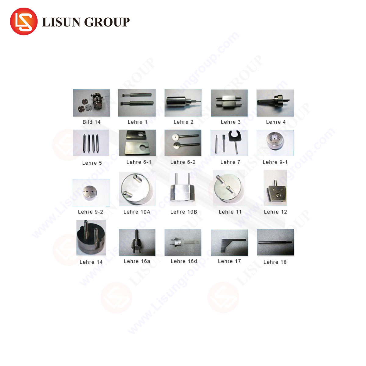
The operational principle is that of a calibrated, physical reference. The gauge set typically includes:
- Socket Gauge (Plug Simulator): A precision-machined artifact that replicates the maximum permissible dimensions of a plug’s pins (earth and live) in terms of length, diameter, spacing, and profile. This gauge is inserted into a socket-outlet under test to verify that the socket’s internal contacts are positioned to achieve the correct mating sequence with this worst-case plug.
- Plug Gauge (Socket Simulator): A complementary artifact that replicates the minimum permissible recess and contact positioning of a socket. This gauge receives a plug under test to verify the plug’s pins are of correct length and alignment to achieve the required sequence with this worst-case socket.
Technical Specifications and Functional Attributes of Advanced Gauge Systems
A modern gauge system like the LISUN series is characterized by several key technical attributes that differentiate it from basic tooling:
- Material Science: Gauges are fabricated from hardened tool steel or high-wear-resistant alloys, often with surface treatments like chromium plating or nitriding to ensure long-term dimensional stability and resist corrosion from repeated use.
- Precision Machining: Tolerances are held to levels significantly tighter than the product standards require (e.g., ±0.01mm on critical lengths and diameters), ensuring the gauge itself does not contribute to measurement uncertainty.
- Integrated Verification Features: High-end systems may incorporate built-in electrical continuity circuits with indicator lights (LED) or audio buzzers. When the socket gauge is inserted, the lights illuminate in a sequence (Earth LED first, then Live LEDs), providing an immediate, unambiguous functional pass/fail result for the FMC test.
- Comprehensive Set Coverage: A complete set conforms to multiple international configurations (e.g., Type A, B, C, D, E, F, G, I, etc., as per IEC, BS, AS/NZS, GB standards), each with specific pin geometries for live, neutral, and earth contacts.
Table 1: Example Specification Range for a Comprehensive Gauge Set
| Parameter | Specification Detail |
| :— | :— |
| Applicable Standards | IEC 60884-1, IEC 60320, BS 1363, AS/NZS 3112, GB 2099.1, etc. |
| Gauge Types | Socket Gauges (for testing sockets), Plug Gauges (for testing plugs) |
| Dimensional Tolerance | Typically within ±0.01mm to ±0.02mm on critical contact length features |
| Material | High-carbon chromium steel, hardened to 58-62 HRC |
| Surface Treatment | Anti-corrosion plating or black oxide finish |
| Verification Method | Mechanical fit, optionally with integrated electrical circuit & visual/audible indicators |
| Covered Plug Types | Comprehensive range including Types A, B, C, D, E, F, G, H, I, J, K, L, N, etc. |
Industry Applications and Integration within Quality Assurance Workflows
The application of these specialized gauges spans the entire product lifecycle within the plugs and sockets industry.
- Research, Development, and Design Validation: Engineers use gauge sets to verify that prototype molds and first articles meet the dimensional intent of the design before committing to full-scale production, ensuring the FMC requirement is inherently designed into the product.
- Incoming Quality Control (IQC): Manufacturers of finished assemblies (e.g., power strips, appliances) use plug gauges to verify that sourced socket components from suppliers are within specification, preventing non-conforming parts from entering the production line.
- In-Process and Final Production Testing: On assembly lines, gauge checks are implemented as a critical control point. A socket gauge test performed on every 10th or 50th outlet provides statistical process control (SPC) data, catching tooling wear or molding process drift before it results in a batch failure.
- Third-Party Laboratory Certification: Testing laboratories such as UL, Intertek, TÜV, and CSA rely on certified master gauge sets as their primary reference for conducting standardized FMC tests during safety certification. The traceability of these gauges to national metrology institutes is crucial for auditability.
- Market Surveillance and Compliance Verification: Regulatory bodies and customs authorities use gauge sets for rapid screening of products in the supply chain to identify non-compliant goods that may pose a safety risk.
Competitive Advantages of Dedicated Gauge Systems over Alternative Methods
The adoption of a purpose-built system like the LISUN Gauges confers several distinct advantages:
- Unambiguous Conformity Assessment: The gauge provides a direct, go/no-go functional test. If a certified socket gauge inserts and the correct electrical sequence is achieved, the socket conforms to the FMC requirement by definition. This eliminates interpretation errors.
- Exceptional Operational Efficiency: A test can be completed in seconds by a minimally trained operator, enabling high-frequency sampling that is impractical with CMMs. This supports lean manufacturing and just-in-time quality principles.
- Reduced Measurement Uncertainty: By consolidating the measurement of multiple interrelated features (pin length, alignment, spacing) into a single functional check, the system minimizes the root-sum-square accumulation of uncertainties inherent in taking multiple discrete measurements.
- Inherent Traceability and Audit Readiness: Certified gauge sets are supplied with calibration certificates from accredited laboratories, providing a clear and defensible paper trail for quality audits and regulatory inspections.
- Durability and Long-Term Cost-Effectiveness: The robust construction ensures a long service life with minimal recalibration intervals, offering a lower total cost of ownership compared to maintaining the specialized software, probes, and operator training for CMM-based measurement of these specific features.
Conclusion: Ensuring Safety Through Precision Metrology
The First Make Contact test remains a non-negotiable pillar of electrical connector safety, a simple principle with profound implications for user protection. Its reliable execution, however, is contingent upon metrological rigor. The evolution from disparate manual measurements to integrated, functional gauge systems represents a significant advancement in quality assurance methodology for the industry. By providing a direct, efficient, and traceable means to validate the critical dimensional parameters governing contact sequencing, dedicated plug and socket gauge systems are not merely measurement tools but essential safety instruments. They bridge the gap between abstract standard requirements and tangible, mass-produced components, ensuring that every connector that enters the market possesses the inherent mechanical design necessary to protect against electric shock, thereby upholding the fundamental covenant of product safety.
FAQ Section
Q1: How often should plug and socket gauges be recalibrated?
A1: Recalibration intervals depend on usage frequency and environmental conditions. For gauges used in daily production checks, an annual calibration by an accredited laboratory is a common industry practice. Gauges used less frequently or as master references may be calibrated biennially. It is critical to follow a documented calibration schedule and maintain a certificate of traceability for audit purposes.
Q2: Can a single gauge set be used for multiple international plug types?
A2: Comprehensive gauge sets are available as kits containing individual, certified gauges for each specific plug type (e.g., Type G (UK), Type I (AU/NZ), Type A/B (North America), etc.). A single physical gauge is typically designed for one specific configuration due to the vastly different pin geometries, lengths, and arrangements defined by each national standard.
Q3: What is the consequence of a failed First Make Contact test in production?
A3: A failure indicates a non-conforming product that does not meet mandated safety standards. The immediate consequence is the quarantine and rejection of the affected batch. Root cause analysis must then be initiated, typically focusing on mold tooling wear, injection molding process parameters (shrinkage, warpage), or issues in the contact stamping and assembly process. Production should not resume until the cause is corrected and subsequent units pass the test.
Q4: Do these gauges test for other requirements besides First Make Contact?
A4: Yes, a full set of plug and socket gauges is designed to verify multiple clauses of the relevant standard. In addition to FMC, they typically check for Last Break Contact (the reverse sequence), correct pin configuration and spacing, protection against access to live parts (e.g., shutter mechanism operation in sockets), and minimum insertion depth.
Q5: How is the electrical continuity check integrated into a mechanical gauge verified for accuracy?
A5: Gauges with integrated electrical indicators contain internal wiring and contact points. The electrical circuit itself must be periodically verified. This is done by using a known resistance or a dedicated circuit tester to ensure the indicator activates at the precise moment of mechanical contact. This functional check is often part of the routine calibration or a daily pre-use verification performed by the operator.