


A Comprehensive Technical Analysis of Electrostatic Discharge Testing in Automotive Applications with a Focus on Connector System Validation
Introduction
The relentless electrification and digitalization of the modern automobile have precipitated a paradigm shift in electromagnetic compatibility (EMC) requirements. Within this complex electromagnetic ecosystem, Electrostatic Discharge (ESD) represents a persistent and insidious threat to vehicle electronic control units (ECUs), sensor arrays, and infotainment systems. ESD events, characterized by transient currents of several amperes and voltages exceeding 30kV, can induce latent damage, soft errors, or catastrophic failure in semiconductor components. Consequently, rigorous ESD testing has transitioned from a general EMC consideration to a critical, non-negotiable validation step in automotive design and manufacturing. This article provides a detailed technical exposition of automotive ESD testing methodologies, with particular emphasis on the validation of connector systems—plugs and sockets—which serve as both potential entry points for ESD transients and critical links in the vehicle’s electronic nervous system. The analysis will incorporate relevant international standards, testing topologies, and the instrumental role of specialized equipment, such as the LISUN Gauges for Plugs and Sockets, in ensuring connector integrity and system-level robustness.
The Electrophysical Nature of Automotive ESD Threats
Automotive ESD threats are predominantly categorized into two discharge models: the Human Body Model (HBM) and the more severe Charged Device Model (CDM). While HBM simulates discharge from a human operator, the CDM is often more relevant to automated production and assembly environments where a device itself becomes charged and discharges rapidly to a grounded conductor. The transient pulse from a CDM event features a faster rise time (sub-nanosecond) and a shorter duration than HBM, posing a significant challenge to the input protection structures of integrated circuits.
In the vehicular context, ESD events can originate from multiple sources: occupant movement across seat fabrics, triboelectric charging during fuel filling, or environmental factors such as wind-blown particulates. These events can couple into vehicle electronics via direct discharge to accessible components (e.g., USB ports, button panels) or through indirect coupling, where the radiated electromagnetic field from a nearby discharge induces currents in wiring harnesses and PCB traces. Connector interfaces, by their very function of providing an electromechanical bridge between subsystems, are particularly vulnerable zones for both direct injection and field coupling.
Standards Framework: ISO 10605 and OEM-Specific Extensions
The cornerstone standard for automotive ESD testing is ISO 10605:2008, “Road vehicles — Test methods for electrical disturbances from electrostatic discharge.” This document meticulously defines test procedures, including the calibration of the ESD generator, test environment requirements (humidity control is critical), and two primary test methods: the contact discharge method and the air discharge method. The standard specifies test voltage levels, which for automotive applications typically range from ±2 kV to ±25 kV for contact discharge and up to ±30 kV for air discharge, depending on the vehicle’s zoning. The interior of the vehicle is often divided into zones with differing severity levels; for instance, a connector behind the dashboard may have a lower requirement than one accessible to the occupant.
However, most Original Equipment Manufacturers (OEMs) supplement ISO 10605 with their own, more stringent corporate standards. These often include additional test pulses, such as the low-inductance, high-current “Cassette Player” pulse defined by some European OEMs, or extended temperature cycling during ESD stress. Furthermore, the International Electrotechnical Commission’s IEC 61000-4-2 standard, while generic, provides the foundational discharge current waveform that informs these automotive-specific adaptations. Compliance, therefore, is not a matter of meeting a single standard but of navigating a matrix of international and OEM-specific requirements.
Connector Systems as the Critical ESD Validation Frontier
Plugs and sockets constitute a primary defense layer against ESD. Their validation encompasses two complementary aspects: the robustness of the connector housing and the integrity of the electrical connection during and after a discharge event. A poorly designed connector can allow an arc to bridge from a charged pin to a sensitive signal line, or its plastic housing can retain a surface charge that alters the discharge path. Moreover, the physical deformation of contacts due to the electromagnetic force (Lorentz force) from a high-current ESD transient can lead to intermittent connections, a failure mode notoriously difficult to diagnose.
Testing connector systems requires a dual approach:
- Direct Discharge Testing: Applying ESD pulses directly to the metallic shells and accessible pins of the connector to simulate a user interaction.
- Indirect/Coupled Testing: Discharging to a horizontal or vertical coupling plane (HCP/VCP) adjacent to a harness terminated with the connector under test, assessing the common-mode noise induced on the cable bundle that the connector must interface with.
The performance metric is not merely survival, but the maintenance of specified electrical characteristics. This necessitates precise measurement of contact resistance, insulation resistance, and dielectric withstanding voltage before, during, and after the ESD test sequence.
Instrumentation for Connector-Centric ESD Validation: The Role of Plug and Socket Gauges
A critical, yet often overlooked, component of a reliable ESD testing regimen for connectors is the verification of the connector’s mechanical dimensions. Imperfect mating, caused by out-of-spec pin geometry or housing warpage, can create micro-gaps that are prime sites for arcing during an ESD event. Furthermore, inconsistent contact force leads to variable contact resistance, which can become a nonlinear element under high transient currents, leading to localized heating and degradation.
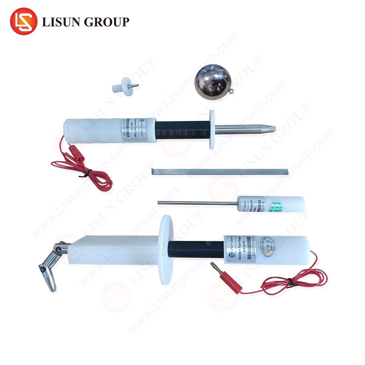
This is where dedicated plug and socket gauges become indispensable laboratory and production tools. Devices like the LISUN Gauges for Plugs and Sockets are engineered to provide quantitative, repeatable measurements of critical connector parameters. Their operation is based on precision mechanical and electrical measurement principles.
Specifications and Testing Principles of LISUN Gauges for Plugs and Sockets
The LISUN gauge system typically comprises a set of precision-machined pin gauges and socket gauges, often crafted from hardened steel or other durable, dimensionally stable materials. Their specifications are traceable to national metrology standards, ensuring accuracy. Key parameters they measure include:
- Pin Diameter and Socket Aperture: Using Go/No-Go gauges or variable measuring pins to verify that contacts are within the tolerance specified by the connector manufacturer (e.g., USCAR or VDA standards).
- Contact Engagement Force: A calibrated gauge pin can be instrumented with a load cell to measure the insertion and extraction force, ensuring it falls within the window that guarantees reliable electrical contact without risking damage to the fragile plating on the contacts.
- Contact Retention Force: For sockets, a gauge pin of specified diameter is used to measure the force required to extract it, validating the spring normal force of the female contact.
- Housing Alignment and Keying: Specialized gauge blocks verify the alignment of guide rails, polarization keys, and locking mechanisms, preventing mis-mating that could expose current-carrying contacts.
The testing principle is one of physical interoperability and specification conformance. By routinely gauging connector samples from production batches, manufacturers can perform Statistical Process Control (SPC), identifying tooling wear or assembly drift before it results in a field failure precipitated by an ESD event.
Industry Use Cases and Integration into the Validation Workflow
The application of connector gauges spans the entire automotive product lifecycle:
- Design Verification: Validating that first article samples from a connector supplier meet the drawing specifications before integration into a prototype ECU or harness.
- Production Incoming Quality Control (IQC): Screening connector lots at the OEM or Tier-1 facility to prevent non-conforming parts from entering the assembly line.
- Failure Analysis: Following an ESD test failure, gauges are used to determine if the root cause was a mechanical defect in the connector interface. A deformed pin may show an out-of-spec engagement force, directly linking the mechanical fault to the electrical failure.
- Tooling Maintenance: Periodic gauge checks of connectors produced by injection molding or stamping presses signal when molds or dies require maintenance.
The competitive advantage offered by a system like the LISUN Gauges lies in its standardization and repeatability. It replaces subjective visual inspections with objective, numerical data. This data can be directly correlated with ESD test results, creating a powerful feedback loop for design improvement. For instance, a correlation might be established between a socket retention force at the lower end of the specification and an increased failure rate during CDM testing, leading to a tightening of the production tolerance.
System-Level ESD Testing Topologies for Electronic Control Units
Beyond the connector itself, system-level testing of an ECU with its connectors is mandatory. The test setup, as per ISO 10605, involves placing the Device Under Test (DUT) on a grounded reference plane, insulated by a thin dielectric. ESD pulses are applied via the generator’s discharge tip to predefined test points—invariably including each connector shell and accessible pins. The DUT is powered and monitored via a monitoring system for functional status during and after the discharge. Two key configurations are employed:
- Direct Discharge to Connector: The most straightforward test, assessing the robustness of the input/output protection circuits on the PCB directly behind the connector.
- Discharge to Coupling Plane with Harness: A more system-representative test where a full or partial wiring harness is connected to the ECU. Discharges are applied to a coupling plane placed parallel to the harness. The resulting induced current travels along the harness and into the ECU via the very connectors being tested, challenging the common-mode filtering and board-level layout.
Data Interpretation and Failure Mode Classification
A pass/fail criterion in ESD testing is based on the performance criteria agreed upon between supplier and OEM, typically Class A, B, C, or D as defined in many EMC standards. Class A denotes no performance degradation; Class B allows for temporary loss of function with self-recovery; Class C requires a manual reset; and Class D is irreversible failure.
For connectors, failure modes are specific:
- Dielectric Breakdown: Arcing across the insulator within the connector housing, carbonizing the plastic and creating a permanent short.
- Contact Welding: The micro-arc at the point of contact during discharge can generate sufficient heat to fuse mating pins, resulting in a stuck connector.
- Surface Contamination Ionization: Residual flux or other contaminants on the connector contacts can ionize, creating a conductive path and leading to leakage currents.
- Latching/Logic Upset: Noise coupled onto signal lines through the connector can cause a microprocessor to latch up or change state.
Correlating these failures with gauge data—such as a marginally undersized pin that created a higher-voltage gap—is a core aspect of forensic engineering in ESD analysis.
Conclusion
Automotive ESD testing is a multidisciplinary challenge that sits at the intersection of electromagnetics, semiconductor physics, and precision mechanical engineering. As data rates increase with the adoption of Automotive Ethernet and the voltage levels rise in electric vehicle powertrains, the severity and complexity of ESD threats will only escalate. A robust validation strategy must therefore be holistic, encompassing not only the application of high-voltage pulses but also the foundational verification of the mechanical interfaces that bind the electronic system together. The integration of quantitative measurement tools, such as plug and socket gauges, into the ESD validation workflow provides an essential data-driven approach to risk mitigation. By ensuring that every connector meets its precise mechanical specification, the probability of an ESD event finding a vulnerable path into sensitive electronics is materially reduced, enhancing the overall quality, reliability, and safety of the modern vehicle.
FAQ Section
Q1: Why is mechanical gauging of connectors considered relevant to an electrical phenomenon like ESD?
A1: The electrical performance of a connector under high-speed transient conditions is intrinsically linked to its mechanical properties. A pin with incorrect geometry or insufficient contact force can create an air gap. During an ESD event, this gap can ionize, creating a low-resistance plasma channel that bypasses designed PCB protection circuits. Gauging ensures consistent, reliable metal-to-metal contact, which provides a controlled, low-impedance path for transient currents to be shunted to ground as intended by the design.
Q2: How frequently should connector gauges be used in a production environment?
A2: The frequency should be determined by a Statistical Process Control (SPC) plan. Initially, gauging may be performed on a first-article basis and then on samples from each production batch (e.g., AQL sampling). The data is tracked for trends. If process capability (Cp/Cpk) indices are high and stable, sampling frequency can be reduced. Any change in tooling, raw material supplier, or a shift in production location should trigger a return to increased gauge verification frequency.
Q3: Can a connector pass gauge checks but still fail system-level ESD testing?
A3: Absolutely. Gauging verifies mechanical conformance, which is a necessary but not sufficient condition for ESD robustness. A failure can still occur due to deficiencies in the PCB layout, inadequate TVS diode selection, insufficient grounding of the connector shield, or software vulnerabilities that cause latch-up. Gauging eliminates mechanical variance as a root cause, allowing engineers to focus troubleshooting efforts on the electronic and systemic design elements.
Q4: What are the key specifications to look for when selecting a plug and socket gauge system for automotive use?
A4: The gauge system must have certified accuracy traceable to national standards (e.g., NIST). Material hardness should exceed that of the contacts being tested to avoid wear. It should cover the full range of critical dimensions: pin/socket size, engagement/retention force, and housing alignment features. Compatibility with the specific automotive connector standards in use (e.g., USCAR-2, LV214, VW 75174) is mandatory. Finally, robustness for use in a production or lab environment is essential.
Q5: How does connector gauging fit into an Automotive SPICE or ASPICE compliant development process?
A5: Within ASPICE processes, particularly in the VDA Scope for hardware development (HWE.1-HWE.6), gauging provides objective evidence for verification activities. It supports “Verification of Hardware Design” (HWE.5) by proving that implemented hardware components (the connectors) meet their specified requirements. The collected gauge data serves as a verification record, demonstrating systematic testing and control of a critical component interface, which is a core tenet of the ASPICE framework for ensuring product quality and reliability.