


Precision Verification in Electrical Connectivity: The Role of Standard Pin Gauges
Introduction to Dimensional Metrology in Electrical Safety
The integrity of electrical connections within plugs, sockets, and connectors is a non-negotiable prerequisite for safety, reliability, and regulatory compliance. A critical, yet often understated, component of this integrity is the precise dimensional conformity of the conductive pins and the receptacles into which they are inserted. Deviations from specified tolerances can lead to a cascade of failures: high-resistance connections causing overheating, intermittent contact leading to arcing and fire hazard, or mechanical strain compromising the product’s lifespan. To mitigate these risks, the industry relies on a fundamental metrological tool: the Standard Pin Gauge. This article provides a comprehensive technical examination of Standard Pin Gauges, their application in verifying plugs and sockets, and the specific implementation exemplified by the LISUN Gauges for Plugs and Sockets product line.
Fundamental Principles of Pin Gauge Application and Force Testing
A Standard Pin Gauge is a cylindrical artifact of precisely calibrated diameter, manufactured to a defined geometric tolerance. Its primary function is not merely to measure, but to verify compliance. The testing principle is one of selective fit. For socket outlet receptacles, the gauge acts as a “Go/No-Go” verification tool. A “Go” gauge, representing the maximum permissible pin size within the tolerance zone, must enter the receptacle under a specified, minimal force to confirm the socket is not undersized. Conversely, a “No-Go” gauge, representing the minimum material condition of the mating pin plus a tolerance, must not enter under its own weight or under a slightly higher specified force, confirming the socket is not oversized to a dangerous degree.
The application of controlled force is paramount. Standards such as IEC 60884-1, BS 1363, and AS/NZS 3112 explicitly define the insertion and withdrawal forces for test pins. Excessive force during a “Go” test may indicate poor contact spring geometry or surface finish issues, while insufficient retention force for a “No-Go” gauge indicates a lack of necessary contact pressure, which can lead to overheating under load. Therefore, the gauge is often used in conjunction with a calibrated force gauge, transforming a simple dimensional check into a functional assessment of the socket’s mechanical and electrical potential. The LISUN system integrates this principle directly, with gauges designed for use with specific force measurement apparatus to ensure standardized, repeatable testing protocols.
Material Science and Manufacturing Tolerances for Gauge Artifacts
The metrological credibility of a pin gauge is contingent upon its own material properties and manufacturing precision. High-carbon chromium steel or tungsten carbide are preferred substrates due to their exceptional hardness, wear resistance, and dimensional stability. Surface finish is critical; a roughness average (Ra) better than 0.2 µm is typically required to prevent the gauge’s own surface imperfections from interfering with the test, simulating the ideal surface of a compliant pin.
Tolerances for the gauge diameters are held to a fraction of the tolerances specified for the components under test. For instance, if a socket contact is designed to accept a pin of 4.0 mm ±0.05 mm, the “Go” gauge might be manufactured to 4.05 mm with a tolerance of ±0.002 mm, and the “No-Go” to 4.10 mm ±0.002 mm. This order-of-magnitude tighter tolerance ensures the gauge acts as an authoritative reference. Furthermore, geometric tolerances for cylindricity and straightness are strictly controlled to prevent a tapered or bowed gauge from providing a false pass or fail result. The LISUN Gauges are manufactured under controlled environmental conditions and are traceable to national metrological institutes, providing an unbroken chain of calibration that underpins their authority in quality assurance and third-party certification testing.
Industry Standards and Regulatory Compliance Frameworks
The design and use of Standard Pin Gauges are inextricably linked to international and national safety standards. These documents do not merely suggest pin dimensions; they legally define them. Key standards include:
- IEC 60884-1: The international baseline for household and similar plugs and socket-outlets.
- BS 1363: The British Standard for 13 A plugs, socket-outlets, and adaptors, with very specific requirements for pin dimensions and earth pin geometry.
- AS/NZS 3112: The Australian/New Zealand standard for Approval and test specification – Plugs and socket-outlets.
- UL 498: The Standard for Safety for Attachment Plugs and Receptacles in North America.
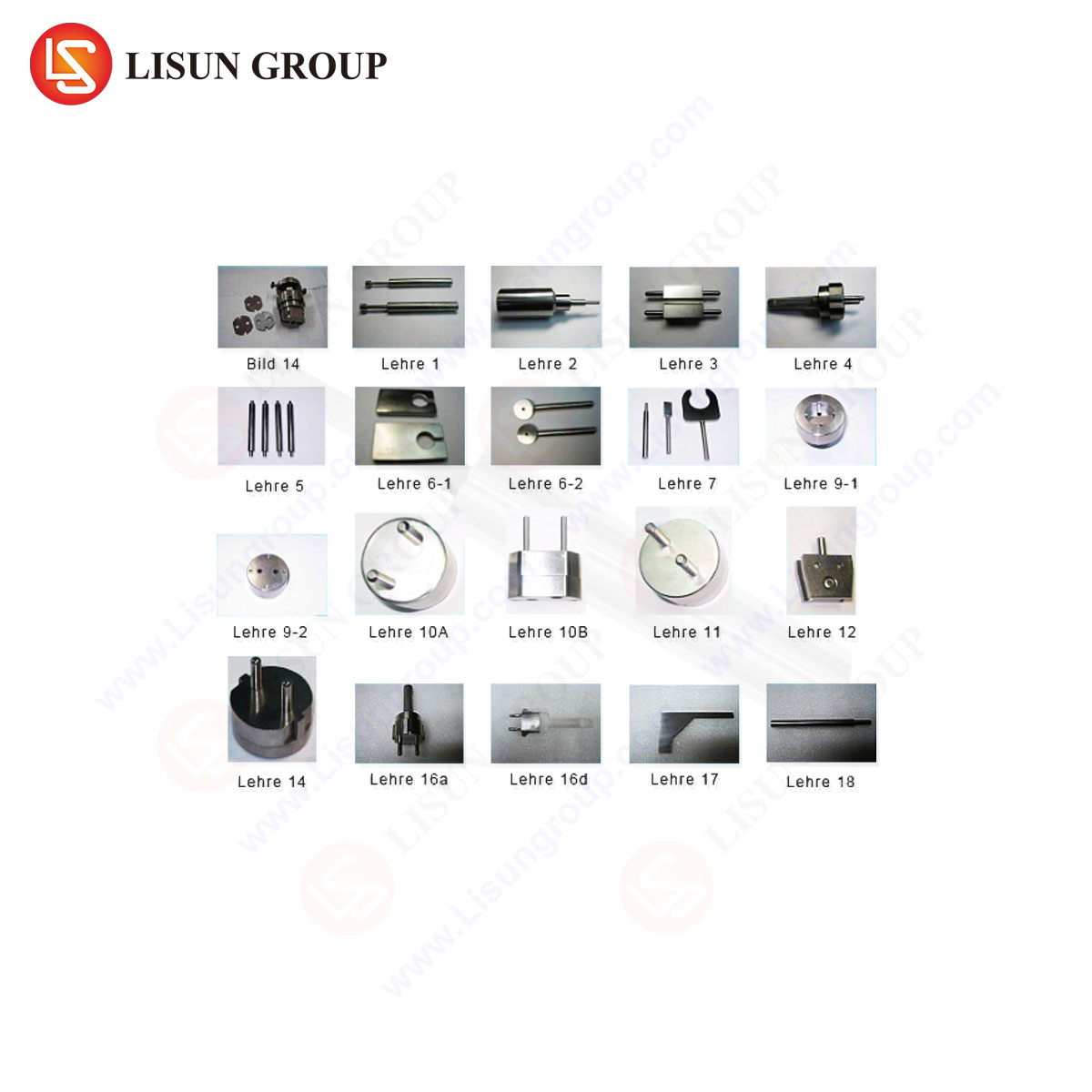
Each standard prescribes unique pin profiles—flat blades, round pins, or rectangular pins with specific chamfers—and corresponding test gauge specifications. A gauge set for BS 1363 compliance, for example, will include not just round live and neutral pin gauges, but also a rectangular earth pin gauge with a defined radius on the corners. The LISUN product catalog is explicitly structured around these standards, offering dedicated kits for IEC, BS, AS/NZS, and other regional requirements, ensuring test laboratories and manufacturers have the correct, standardized artifacts for their target markets.
The LISUN Gauges for Plugs and Sockets: A Technical Specification Overview
The LISUN Gauges for Plugs and Sockets system embodies the technical requirements discussed. It is a modular system designed for comprehensive testing of both socket outlets and plug pins.
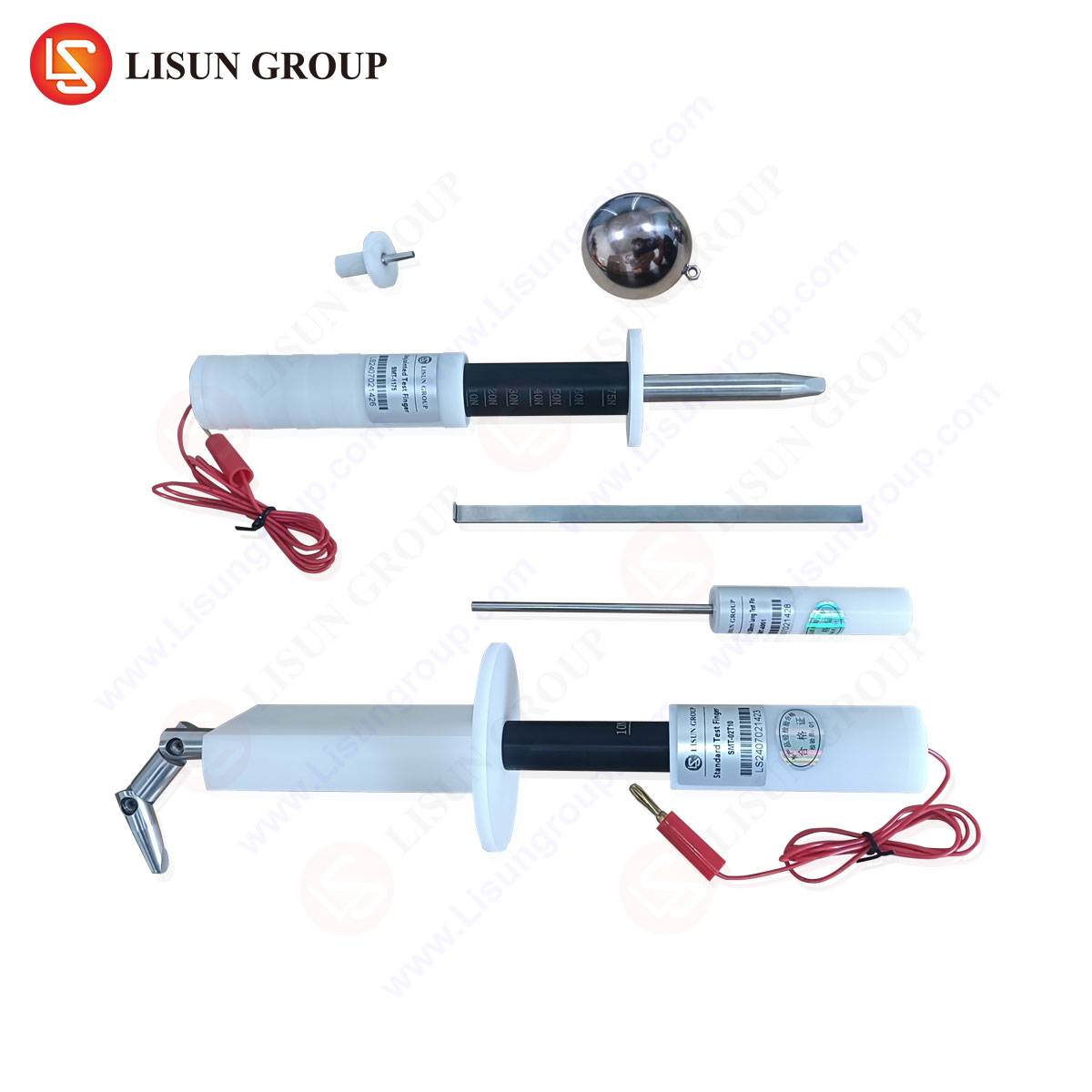
For Socket-Outlet Testing: The system provides “Go” and “No-Go” gauges for each current-carrying contact (live, neutral, earth). Each gauge is mounted on a dedicated handle marked with its function and nominal size. The handles are ergonomically designed for consistent axial alignment during insertion. Crucially, the system includes a set of weights or is compatible with a digital force gauge (model LS-FG01, for example) to apply the exact forces stipulated in Clause 19 of IEC 60884-1 and its regional derivatives. A typical test sequence involves applying the “Go” gauge with a force not exceeding 1 N to verify access, followed by verifying that the “No-Go” gauge cannot enter under a force of 20 N.
For Plug Pin Verification: Separate anvil-style gauges are provided to check the cross-sectional dimensions of plug pins. These are precision-ground blocks with calibrated holes into which the plug pin must fit under its own weight (“Go”) or must not fit (“No-Go”).
Table 1: Example Specification for a BS 1363-Compatible LISUN Gauge Set
| Component | Function | Nominal Dimension | Tolerance | Applied Force (Test Clause) |
| :— | :— | :— | :— | :— |
| Live Pin Gauge | Go | 6.35 mm | ±0.002 mm | ≤ 1 N (Insertion) |
| Live Pin Gauge | No-Go | 6.70 mm | ±0.002 mm | 20 N (Non-Insertion) |
| Earth Pin Gauge | Go | 7.85 mm x 3.05 mm | ±0.002 mm | ≤ 1 N (Insertion) |
| Force Gauge | Measurement | 0-50 N | ±0.5% F.S. | As per standard |
Operational Workflow in a Quality Assurance Laboratory
In a manufacturing or certification laboratory environment, the LISUN gauges are deployed within a rigorous workflow. For incoming inspection of socket components, a statistically significant sample is subjected to the gauge test. The operator first visually inspects the gauge for damage or contamination, then meticulously inserts the “Go” gauge into each contact, monitoring the force gauge readout. A pass is recorded only if insertion is smooth and the peak force remains below the threshold. The “No-Go” test follows, with the operator applying increasing force up to the standard’s limit; any entry constitutes a failure. This data is logged, often with serial numbers, to create an auditable trail of compliance. The process is repeated for plug pins using the anvil gauges. This systematic approach isolates dimensional faults from other assembly or material issues, providing clear, actionable feedback to production lines.
Failure Mode Analysis and Corrective Action Implications
A failure during pin gauge testing is a direct indicator of a specific manufacturing defect. The nature of the failure dictates the root cause investigation.
- “Go” Gauge Failure (Does Not Enter): This indicates undersized socket contacts or oversized plug pins. Potential root causes include incorrect tooling wear in stamping or molding processes, heat treatment distortion, or plating thickness exceeding specifications. For sockets, it may point to a faulty or misaligned contact spring assembly.
- “No-Go” Gauge Failure (Enters Too Easily): This is a critical safety failure, indicating an oversized socket contact or undersized plug pin. This leads to insufficient contact pressure. Causes can include excessive material removal during machining, spring fatigue or incorrect tempering, or fundamental design errors in the contact geometry.
The immediacy and clarity of the gauge test allow for rapid containment—the quarantining of non-conforming batches—and prompt initiation of corrective actions on the production floor, such as tooling replacement or process parameter adjustment.
Competitive Advantages of a Standardized, Traceable Gauge System
The value proposition of a system like LISUN’s extends beyond the provision of hardened steel pins. It lies in the integration of standard compliance, metrological traceability, and operational reliability. Firstly, by offering kits tailored to specific standards, it eliminates the risk of using incorrect gauges, which could lead to false certifications. Secondly, each gauge is supplied with a calibration certificate from an accredited laboratory, tracing its dimensions back to the International System of Units (SI). This is a mandatory requirement for any laboratory operating under ISO/IEC 17025 accreditation. Thirdly, the robust construction and wear-resistant materials ensure gauge longevity and consistency over thousands of test cycles, protecting the investment and ensuring long-term test result stability. This combination reduces compliance risk, accelerates time-to-market for new products, and provides defensible evidence during regulatory audits or product liability assessments.
Conclusion
The Standard Pin Gauge is a deceptively simple tool that performs a critical gatekeeping function in the ecosystem of electrical safety. By providing an unambiguous, force-quantified assessment of the dimensional interface between plug and socket, it serves as a primary defense against connection-related failures. The implementation of a comprehensive, traceable, and standard-specific system, as exemplified by the LISUN Gauges for Plugs and Sockets, transforms this basic principle into a robust quality assurance pillar. For manufacturers, test houses, and certification bodies, such systems are not an optional accessory but a fundamental instrument for ensuring product safety, reliability, and global market access.
Frequently Asked Questions (FAQ)
Q1: How often should LISUN Pin Gauges be recalibrated?
A1: Recalibration frequency depends on usage intensity and the quality management system requirements. For high-volume testing laboratories, an annual calibration cycle is typical. However, if gauges are subjected to accidental impact or show any signs of wear or damage, immediate recalibration is mandatory. The calibration interval should be justified based on historical stability data as per ISO/IEC 17025 guidelines.
Q2: Can one set of LISUN gauges be used to test products for multiple international markets?
A2: No. Pin dimensions and tolerances differ between standards (e.g., BS 1363 vs. AS/NZS 3112 vs. UL 498). Using a gauge designed for one standard to test a product for another will yield invalid and potentially unsafe results. It is essential to use the gauge kit specifically designed and calibrated for the target standard.
Q3: What is the significance of the applied force during testing, and why is a force gauge necessary?
A3: The force specification simulates real-world insertion conditions and tests the functional elasticity of the socket contact. A “Go” test with excessive force indicates high friction and potential overheating. A “No-Go” test that enters with low force indicates dangerous lack of contact pressure. A manual “feel” test is subjective and non-repeatable. A calibrated force gauge provides the objective, quantifiable data required for compliance with standardized test clauses.
Q4: Besides dimensional checks, what other tests are required for full socket compliance?
A4: Pin gauge testing is a fundamental mechanical test, but full compliance requires a suite of electrical and environmental tests. These include, but are not limited to, dielectric strength testing (hipot), grounding continuity testing, temperature rise testing under load, durability testing (insertion/withdrawal cycles), and resistance to heat, arcing, and environmental stress. Pin gauge verification is often the first step in this sequence.