


Evaluating Fire Hazard Resistance: The Role of Glow-Wire Testing in Product Safety Compliance
The imperative to mitigate fire risks in electrical and electronic equipment constitutes a fundamental pillar of global product safety regulations. Among the suite of standardized assessments designed to evaluate a material or component’s resistance to ignition, the glow-wire test stands as a critical, simulation-based methodology. This procedure does not assess flammability in a conventional sense but rather evaluates the ability of an end-product or its constituent parts to withstand thermal stress caused by overheated or glowing elements under fault conditions, without propagating fire. The equipment engineered to perform these tests must deliver precise, repeatable, and fully compliant thermal insults to specimens, thereby generating reliable data for safety certification. This technical examination delves into the principles, standards, and implementation of glow-wire testing, with a focused analysis on a representative apparatus: the LISUN ZY-3 Needle Flame Test Instrument.
Fundamental Principles of the Glow-Wire Ignition Test
The core objective of the glow-wire test is to simulate a scenario where an electrical component, due to overload, poor contact, or failure, reaches an elevated temperature and begins to glow. This glowing element may then contact adjacent insulating materials or structural parts. The test apparatus artificially recreates this condition using a standardized heating element, typically a loop of nickel/chromium (80/20) wire of specified dimensions, which is electrically heated to a predetermined temperature. This heated element—the “glow-wire”—is then applied with a defined force against the test specimen for a precise period.
The evaluation criteria are multifaceted. Technicians observe whether the specimen ignites and, if so, the duration of any flames (flame persistence time). They also note whether dripping particles occur and if these drips ignite a single layer of tissue paper positioned below the specimen, a key indicator of secondary fire hazard. The specimen’s ability to self-extinguish and its structural integrity post-test are critical pass/fail determinants. This test, therefore, provides a quantifiable measure of a product’s resilience against a specific, realistic thermal fault, informing design choices in material selection, geometry, and component spacing.
Governing Standards and Their Industrial Implications
Glow-wire testing is not a singular procedure but a family of tests detailed in several international and regional standards, primarily the IEC 60695-2 series. IEC 60695-2-10, -11, -12, and -13 outline the requirements for the glow-wire apparatus, the basic test method, the glow-wire flammability index (GWFI), and the glow-wire ignition temperature (GWIT), respectively. The GWFI is the highest temperature at which a material does not ignite or, if it does, extinguishes within 30 seconds after removal of the glow-wire without causing part ignition. The GWIT is the temperature 25°C or 30°C (depending on the temperature increment) above the maximum test temperature at which the material does not ignite for a duration of at least 5 seconds.
Compliance with these standards is mandated across a vast spectrum of industries. For Electrical and Electronic Equipment and Household Appliances (e.g., circuit breakers, appliance housings), adherence to IEC 60695 is often a prerequisite for CE marking or UL certification. In Automotive Electronics, where components are housed in confined spaces with potential for heat buildup, similar tests per ISO 20653 or internal OEM specifications are vital. Lighting Fixtures, particularly those using high-intensity LEDs or housed in plastic enclosures, must demonstrate that a fault in the driver or connector will not lead to enclosure ignition. Medical Devices and Aerospace and Aviation Components demand even more rigorous scrutiny, where failure consequences are severe, and material performance under thermal stress is integral to system safety. The test is equally relevant for discrete Electrical Components like switches, sockets, and connectors, as well as the insulation and jacketing materials used in Cable and Wiring Systems.
Architectural Overview of Modern Glow-Wire Test Apparatus
A contemporary glow-wire test instrument is an integrated system of precision subsystems. The central component is the glow-wire tip assembly, mounted on a movable arm. This arm allows for precise, reproducible application of the tip onto the specimen. The apparatus incorporates a high-precision temperature measurement and control system, typically using a Type K (chromel-alumel) thermocouple spot-welded to the glow-wire tip, ensuring the set temperature (ranging from 550°C to 960°C or beyond) is maintained within tight tolerances (± 10°C per IEC standard).
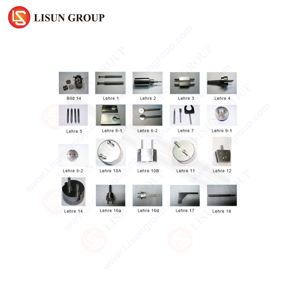
A calibrated weight system applies the required contact force (1.0 N ± 0.2 N) to the specimen. The test chamber is designed to minimize air drafts while providing observation access. Critical to the apparatus is the specimen support and positioning system, which must accommodate products of various sizes and geometries as stipulated by the end-product standard. Furthermore, a timing system automates the application duration (typically 30 seconds) and records flame persistence times. Advanced units integrate data acquisition systems to log temperature profiles, application times, and other test parameters, enhancing traceability and audit readiness.
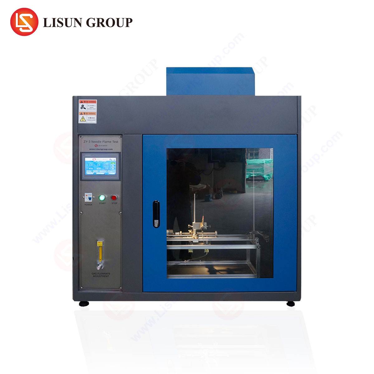
The LISUN ZY-3 Needle Flame Test Instrument: A Technical Analysis
The LISUN ZY-3 Needle Flame Test Instrument represents a specialized implementation of thermal fault simulation testing, conforming primarily to the needle-flame test method prescribed in IEC 60695-11-5, IEC 60695-2-2, and related standards (e.g., GB/T 5169.5). While distinct from the traditional glow-wire test, it addresses a similar hazard profile—small flames resulting from faulty conditions—and shares technological DNA with glow-wire apparatus in its control and measurement philosophy. It is designed to verify the fire hazard posed by small flames that may result from malfunction within electrotechnical equipment.
Testing Principle: The ZY-3 generates a controlled needle flame via a specific burner fed with a prescribed fuel (e.g., butane). The flame is applied to the test specimen for a defined period (e.g., 30 seconds). Observations mirror those of the glow-wire test: ignition, flame duration, and the ignition capability of dripping particles. This test is particularly relevant for evaluating small components, printed circuit boards (PCBs), and internal wiring assemblies where a small, localized flame is the credible risk.
Specifications and Competitive Advantages:
- Precision Flame Control: The instrument employs a calibrated burner and mass flow control to maintain a stable flame height of 12mm ± 1mm, a critical parameter for test reproducibility.
- Automated Test Cycle: Programmable application and duration timers remove operator variability, ensuring consistent flame exposure times.
- Integrated Safety and Observation: A clear test chamber with draft shielding protects the flame from disturbances while allowing full visibility. Safety features often include gas leak detection and automatic shut-off.
- Versatile Specimen Fixturing: The design accommodates a range of specimen sizes and shapes, crucial for testing diverse products from telecommunications equipment enclosures to internal industrial control systems modules.
- Comprehensive Data Recording: Advanced models facilitate the recording of test parameters and outcomes, supporting rigorous quality documentation.
The competitive advantage of an instrument like the ZY-3 lies in its dedicated design for the needle-flame standard. Its focused functionality ensures optimal compliance with IEC 60695-11-5 requirements, often at a lower complexity and cost point than a full multi-function combustion tester. For manufacturers of consumer electronics, office equipment, and electrical components where this specific test is mandated, it provides a reliable, purpose-built solution.
Operational Protocol and Data Interpretation
A standardized test sequence begins with specimen conditioning, typically at 23°C ± 2°C and 50% ± 5% relative humidity for a minimum period. The glow-wire or needle flame is then stabilized at the target temperature. The specimen is positioned according to the relevant end-product standard—this may involve vertical, horizontal, or a custom orientation to simulate real-world assembly. The heated element is applied, and the observation period commences.
Data interpretation is strictly rule-based. For a GWFI determination, a “pass” is concluded if no ignition occurs, or if flames and/or glowing of the specimen extinguish within 30 seconds after removal of the glow-wire, and no dripping particles ignite the tissue paper. The GWIT requires that no ignition occurs for at least 5 seconds at the test temperature. These indices become material properties that designers reference. A switch manufacturer, for instance, will select a polymer for its housing with a GWFI and GWIT rating that exceeds the maximum possible fault temperature estimated for the internal contacts, building in a necessary safety margin.
Integration into a Broader Product Safety Strategy
Glow-wire and needle-flame testing are not isolated activities but integral components of a holistic product safety engineering process. The results directly inform Failure Mode and Effects Analysis (FMEA) and risk assessments required by frameworks like ISO 14971 for medical devices. In automotive electronics, the data feeds into the component qualification process, supporting compliance with functional safety standards such as ISO 26262.
Material suppliers use these tests to grade and certify their products, providing datasheet values (GWFI, GWIT) to downstream manufacturers. An aerospace component supplier will perform these tests as part of a broader suite of environmental stress screenings. Ultimately, the data generated by this equipment provides objective evidence to Notified Bodies, certification labs, and internal audit teams that a product’s fire hazard has been adequately assessed and mitigated through design.
Future Trajectories in Fire Hazard Testing Technology
The evolution of glow-wire test equipment is aligned with broader trends in laboratory instrumentation: increased automation, enhanced data integrity, and deeper integration with quality management systems. Future iterations may feature more sophisticated vision systems for automated flame detection and persistence timing, reducing human observational error. Integration with Laboratory Information Management Systems (LIMS) for seamless data upload and report generation is another likely development.
Furthermore, as material science advances with new composites and flame-retardant chemistries, test standards may evolve, requiring apparatus adaptability. The drive for miniaturization in consumer electronics and medical devices may necessitate refined test methods for smaller components, pushing equipment manufacturers to develop precise fixtures and application mechanisms. The core principle, however—simulating a credible thermal fault with repeatable severity—will remain the unchanging mandate of this critical safety evaluation technology.
FAQ Section
Q1: What is the key difference between the Glow-Wire Test (IEC 60695-2-11) and the Needle-Flame Test (IEC 60695-11-5) performed by an instrument like the LISUN ZY-3?
The fundamental difference lies in the simulated fault. The glow-wire test uses a solid, electrically heated element to simulate contact with an overheated or glowing conductive part. The needle-flame test uses a small, open gas flame to simulate the effect of a small flaming element. The choice of test is dictated by the specific hazard analysis and the requirements of the end-product safety standard.
Q2: For a plastic housing of a power supply unit, which rating is more critical to obtain: Glow-Wire Flammability Index (GWFI) or Glow-Wire Ignition Temperature (GWIT)?
Both provide valuable but different information. The GWFI indicates the material’s performance when subjected to the glow-wire at a specific temperature, including its behavior regarding ignition and dripping. The GWIT provides a temperature threshold below which the material will not ignite from the glow-wire. For a complete safety assessment, particularly for certification to standards like IEC 60335 (household appliances), both indices are often required and specified in the material requirements.
Q3: How often should the glow-wire tip or needle-flame burner be calibrated, and what does calibration involve?
Calibration frequency should follow the laboratory’s quality procedure, typically every 6 to 12 months, or after a specified number of tests or any maintenance. Calibration involves verifying the temperature measurement system’s accuracy against a traceable standard for the glow-wire. For the needle flame, it involves verifying the flame height and temperature profile using a calibrated thermocouple and gauge. Gas flow rate may also be checked.
Q4: Can the same test specimen be used for multiple glow-wire applications?
No. Each test application causes irreversible thermal degradation and charring, altering the material’s properties. Each data point (e.g., for determining GWFI at a specific temperature) must be obtained from a fresh, unused specimen that has been properly conditioned. Multiple tests are performed on separate specimens to establish the material’s rating.
Q5: In the context of automotive electronics, are glow-wire tests performed on the final assembled module or on material plaques?
Both approaches are used, governed by different standards. Material qualification (e.g., per ISO 6722 for cables) often uses standardized plaques to establish baseline properties. However, end-product testing per automaker-specific specifications or standards like LV 124 may require testing on the final assembled component or a representative section thereof to account for the effects of geometry, wall thickness, assembly stresses, and the presence of other materials.