


High-Precision AC DC Digital Power Meter for Automotive Electronics Testing
Abstract
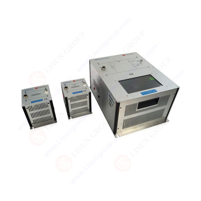
The high-precision AC DC digital power meter represents a critical advancement in electrical testing for automotive electronics validation. These instruments combine digital sampling waveform analysis with automatic range switching to deliver accurate measurements across AC and DC systems. Core value lies in their ability to measure voltage, current, power, power factor, and harmonics with exceptional precision, supporting compliance testing against standards including EN/IEC61000-3-2 and LM-79. For automotive electronics testing, R&D validation, and EMC compliance laboratories, these meters provide essential capabilities for power quality analysis, harmonic assessment, and component characterization. This article examines the technical architecture, model variations including LS2050B, LS2050C, and LS2050C-IEC, and practical applications for electrical testing engineers in automotive and LED manufacturing industries.
1. Technical Architecture of Precision Power Measurement
1.1 Digital Sampling Waveform Analysis
High-precision AC DC digital power meters employ advanced digital sampling techniques to capture and analyze electrical waveforms with high fidelity. The sampling system converts analog voltage and current signals into digital data at rates sufficient to reconstruct waveforms accurately for frequencies up to 100 kHz. This approach enables simultaneous measurement of multiple parameters including RMS voltage, RMS current, active power, apparent power, reactive power, and power factor. The digital architecture supports real-time waveform display and data logging, giving engineers visibility into transient events and non-sinusoidal conditions common in automotive electronic systems such as switching power supplies and motor drives.
1.2 Automatic Range Switching Technology
Automatic range switching eliminates the need for manual range selection, reducing measurement errors and improving testing efficiency. The meter continuously monitors input signals and selects the optimal measurement range for voltage and current channels. This dynamic range management ensures that measurements remain within the instrument’s most accurate operating region, even when testing devices with widely varying power consumption profiles. For automotive electronics testing, where components may operate in standby mode consuming milliwatts and then surge to hundreds of watts during active operation, automatic range switching maintains measurement integrity across the entire operating envelope without operator intervention.
1.3 Harmonic Analysis Capabilities
Harmonic analysis is a core feature of these precision instruments, enabling assessment of power quality and compliance with harmonic emission standards. The meters perform total harmonic analysis for up to 50 harmonics using both IEC and CSA calculation methods. The analysis engine computes individual harmonic magnitudes, phase angles, and total harmonic distortion (THD) for both voltage and current waveforms. This capability is essential for automotive electronics testing, where power converters, inverters, and electronic control units generate harmonic currents that must be characterized for EMC compliance and system integration validation.
2. Model Variations and Performance Specifications
2.1 LS2050B Standard Accuracy Model
The LS2050B model provides standard accuracy suitable for production testing and quality control applications. This instrument delivers reliable measurements for voltage, current, and power parameters across the full AC and DC operating range. The standard accuracy configuration supports harmonic analysis and automatic range switching while offering a cost-effective solution for manufacturing environments. For LED driver testing and automotive component validation where moderate precision is acceptable, the LS2050B provides a balanced combination of performance and value, supporting communication via RS232 and RS485 ports for integration into automated test systems.
2.2 LS2050C High Accuracy Model
The LS2050C model achieves enhanced accuracy specifications for demanding R&D and certification testing applications. This instrument incorporates refined measurement circuitry and calibration techniques to reduce measurement uncertainty. The high accuracy version is particularly valuable for automotive electronics validation where tight tolerance specifications require measurement confidence. Engineers performing power efficiency characterization, standby power measurement, or component derating analysis benefit from the improved accuracy margins. The LS2050C maintains full harmonic analysis capabilities and automatic range switching while delivering the precision necessary for research and development environments.
2.3 LS2050C-IEC EMC Compliance Model
The LS2050C-IEC variant is specifically configured for EMC harmonic compliance testing according to EN/IEC61000-3-2 requirements. This model incorporates specialized firmware algorithms and measurement filters that align with the testing procedures specified in the standard. The instrument supports the full test methodology including measurement window timing, statistical analysis, and compliance evaluation against harmonic current limits. For EMC testing laboratories and automotive electronics manufacturers requiring formal compliance certification, the LS2050C-IEC provides a complete solution that meets the rigorous requirements of international harmonic emission standards.
Table 1: Technical Specification Comparison Across Power Meter Models
| Parameter | LS2050B | LS2050C | LS2050C-IEC |
|---|---|---|---|
| Voltage Accuracy (AC) | ±0.1% of reading + 0.1% of range | ±0.05% of reading + 0.05% of range | ±0.05% of reading + 0.05% of range |
| Current Accuracy (DC) | ±0.1% of reading + 0.1% of range | ±0.05% of reading + 0.05% of range | ±0.05% of reading + 0.05% of range |
| Power Accuracy | ±0.2% of reading + 0.2% of range | ±0.1% of reading + 0.1% of range | ±0.1% of reading + 0.1% of range |
| Harmonic Analysis Range | 0-50 harmonics | 0-50 harmonics | 0-50 harmonics (IEC method) |
| Frequency Measurement Range | 0.5Hz – 100kHz | 0.5Hz – 100kHz | 0.5Hz – 100kHz |
| Maximum Voltage (Instantaneous) | 1600V | 1600V | 1600V |
| Maximum Current (Instantaneous) | 50A | 50A | 50A |
| Communication Interfaces | RS232, RS485 | RS232, RS485 | RS232, RS485 |
| EMC Harmonic Compliance | Standard analysis | Standard analysis | EN/IEC61000-3-2 compliant |
| Primary Application | Production testing | R&D validation | Certification testing |
3. Measurement Parameters and Data Acquisition
3.1 Core Electrical Parameters
The high-precision AC DC digital power meter measures fundamental electrical parameters with exceptional accuracy across both AC and DC operating modes. Voltage measurement covers DC and AC waveforms with frequency response from 0.5 Hz to 100 kHz, accommodating everything from power line frequencies to high-frequency switching converters found in automotive electronics. Current measurement similarly spans the full frequency range with automatic range selection ensuring optimal resolution. Power measurements include active power (watts), apparent power (volt-amperes), and reactive power (VAR), providing complete visibility into energy transfer and utilization efficiency.
3.2 Power Quality and Power Factor Analysis
Power factor measurement includes both displacement factor (cosine of the phase angle between fundamental voltage and current) and true power factor (ratio of active to apparent power including harmonic content). This distinction is critical for automotive electronics testing where non-linear loads create significant harmonic distortion. The displacement factor helps engineers separate fundamental reactive power from harmonic-induced power quality issues. The instrument simultaneously computes power factor, phase angle, and frequency for each measurement cycle, enabling comprehensive power quality assessment that supports EMC troubleshooting and system optimization.
4. Automotive Electronics Testing Applications
4.1 Powertrain and Motor Drive Validation
Automotive electronics testing requires precise power measurement for electric vehicle powertrain components including traction inverters, DC-DC converters, and electric motors. The high-precision AC DC digital power meter measures input DC power from the battery and output AC power to the motor, enabling efficiency calculations critical for range optimization and thermal management. The wide frequency range captures switching harmonics and ripple currents that affect system performance. Engineers use harmonic analysis to evaluate pulse-width modulation strategies and filter design effectiveness, ensuring powertrain systems meet performance targets and electromagnetic compatibility requirements.
4.2 Electronic Control Unit Power Characterization
Modern vehicles contain dozens of electronic control units that must be characterized for power consumption across operating modes including active, idle, and sleep states. The digital power meter measures the milliwatt-level consumption in standby modes while maintaining accuracy for peak currents during processor activation and communication events. Automatic range switching is essential for this application, as power levels can vary by several orders of magnitude between operating states. The RS232 and RS485 communication ports enable integration with automated test sequences, allowing comprehensive power profiling across multiple operating conditions without manual intervention.
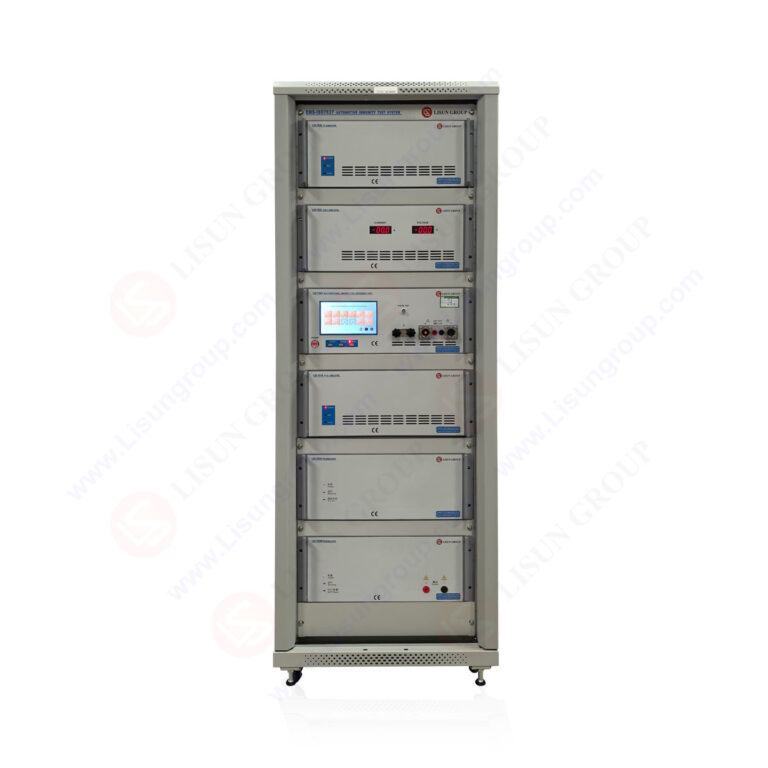
4.3 EMC Harmonic Compliance Testing
Automotive electronics must comply with harmonic emission limits specified in international standards. The LS2050C-IEC model is specifically designed for EN/IEC61000-3-2 compliance testing, which sets limits for harmonic currents injected into the AC power supply by equipment rated up to 16 amps per phase. The instrument performs the required measurement procedures including statistical analysis over specified observation periods. For automotive electronics manufacturers supplying components to OEMs, documented harmonic compliance is essential for system-level certification. The power meter provides the measurement traceability and reporting capabilities necessary for formal compliance documentation.

5. Compliance Standards and Certification Requirements
5.1 EN/IEC61000-3-2 Harmonic Emission Limits
The EN/IEC61000-3-2 standard establishes limits for harmonic currents injected by equipment connected to public low-voltage distribution systems. This standard classifies equipment into four categories (A, B, C, D) with specific harmonic current limits for each class. Automotive electronics testing equipment must measure individual harmonic components up to the 40th harmonic with sufficient accuracy to demonstrate compliance with these limits. The LS2050C-IEC implements the measurement methodology specified in the standard, including the use of a reference impedance and statistical evaluation over a 2.5-minute observation period, ensuring test results are acceptable for formal certification.
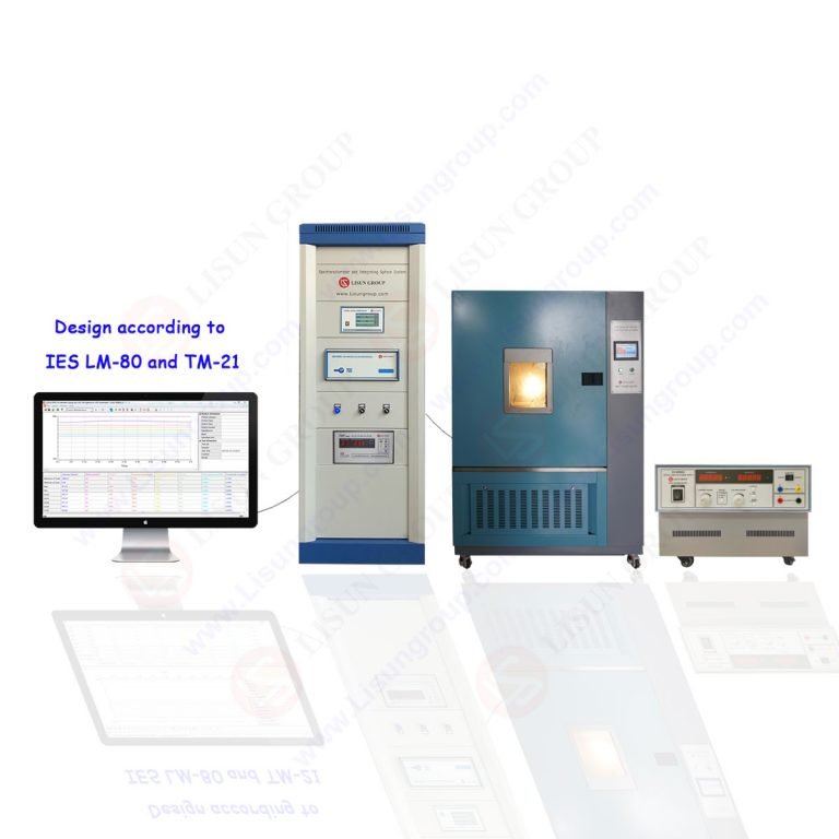
5.2 LM-79 and IEC 61010 Compliance
LM-79 standard specifies electrical and photometric measurements for solid-state lighting products, requiring power measurements with accuracy better than 0.5% for total harmonic distortion and power factor. The high-precision AC DC digital power meter meets these requirements, supporting LED manufacturing testing alongside automotive applications. IEC 61010 establishes safety requirements for electrical test and measurement equipment, covering creepage distances, clearance distances, and protection against electrical shock. The instrument’s design incorporates voltage and current overload protection up to 1600V and 50A instantaneous maximums, providing operator safety and equipment protection during fault conditions.
5.3 UL 1989 and CIE Certification
UL 1989 addresses the safety of standby batteries for emergency lighting and power equipment. While primarily a safety standard, compliance testing involves electrical measurements that benefit from high-precision instrumentation. The power meter’s capability to measure DC parameters accurately supports battery characterization and charger efficiency testing. CIE certification relates to international Commission on Illumination standards for photometric measurements, which require simultaneous electrical and optical measurements. The instrument’s communication ports enable integration with photometric measurement systems, supporting combined electrical-optical characterization in single test setups.
6. Hardware Features and System Integration
6.1 High Overload Capacity and Protection
The high-precision AC DC digital power meter incorporates robust overload protection to withstand fault conditions common in testing environments. The voltage input handles instantaneous peaks up to 1600V, while the current input manages peaks up to 50A. This over-range capability protects the instrument during inrush current testing, short-circuit conditions, or switching transients in automotive power systems. The protection circuits operate automatically, engaging within microseconds to prevent damage while maintaining measurement integrity under normal conditions. For engineers testing prototype circuits or troubleshooting existing designs, this robustness reduces the risk of instrument damage and associated downtime.
6.2 Communication Interfaces and Data Management
RS232 and RS485 communication ports provide connectivity options for different test system architectures. RS232 offers simple point-to-point connection for direct integration with a single computer or data logger, suitable for benchtop testing and calibration applications. RS485 enables multi-drop networks where multiple power meters communicate over a single bus, ideal for production test lines with multiple test stations. Both interfaces support standard protocols for remote control, data acquisition, and configuration management. The ability to integrate with automated test equipment and data management systems streamlines documentation and reporting for compliance testing.
6.3 Display and User Interface Design
The instrument’s front panel provides clear presentation of measurement results with simultaneous display of multiple parameters. Engineers can configure the display to show voltage, current, power, power factor, and harmonic data in formats tailored to specific testing requirements. Numerical values appear with appropriate resolution and units, while graphical displays show waveform shapes and harmonic spectra for visual analysis. The user interface supports configuration of measurement parameters, data logging intervals, and communication settings without requiring external software. This standalone operation capability is valuable for field testing and troubleshooting applications.
7. Best Practices for Precision Power Measurement
7.1 Measurement Setup and Connection Considerations
Achieving optimal measurement accuracy requires careful attention to test setup including proper wiring, grounding, and load connections. Voltage measurements should use the four-wire Kelvin connection method when measuring low resistance or high current circuits to eliminate lead resistance errors. Current transformers or shunts must be selected with appropriate bandwidth and accuracy for the frequency range under test. For automotive electronics testing, ground loops can introduce measurement errors, particularly at higher frequencies. Engineers should use isolated measurements when testing circuits with different ground references, and verify instrument calibration before critical measurements.
7.2 Data Interpretation and Error Analysis
Understanding measurement uncertainty sources enables engineers to interpret results correctly and make informed decisions. The instrument’s specified accuracy includes contributions from gain errors, offset errors, and linearity deviations that vary with measurement range and signal characteristics. For harmonic measurements, amplitude accuracy degrades at higher harmonic orders due to bandwidth limitations and anti-aliasing filter characteristics. Engineers should document measurement conditions including range settings, signal levels, and environmental factors to enable proper uncertainty analysis. When comparing measurements between different instruments or test setups, systematic differences should be characterized through correlation studies.
8. Conclusion
The high-precision AC DC digital power meter provides essential measurement capabilities for automotive electronics testing, EMC compliance validation, and power quality analysis. The combination of digital sampling waveform analysis, automatic range switching, and comprehensive harmonic analysis up to 50 harmonics enables accurate characterization of complex electrical systems. Model variations including LS2050B, LS2050C, and LS2050C-IEC offer options optimized for production testing, R&D validation, and formal compliance certification respectively, allowing engineers to select appropriate performance levels for specific applications.
Compliance with international standards including EN/IEC61000-3-2, LM-79, IEC 61010, and UL 1989 ensures that measurement results are acceptable for formal certification and regulatory submissions. The wide frequency range from 0.5 Hz to 100 kHz accommodates diverse testing requirements from fundamental power frequency analysis through high-frequency switching characterization. Communication interfaces supporting RS232 and RS485 enable integration with automated test systems, while high overload capacity provides protection in demanding test environments.
For electrical testing engineers, quality control managers, and R&D professionals in automotive and LED manufacturing industries, these instruments deliver the measurement confidence necessary for product validation, compliance demonstration, and performance optimization. The technical capabilities address the increasing complexity of modern electronic systems while maintaining the accuracy and reliability required for critical engineering decisions.
FAQ (Frequently Asked Questions)
Q1: What is the difference between displacement power factor and true power factor measurements in automotive electronics testing?
A: Displacement power factor measures the cosine of the phase angle between the fundamental voltage and current waveforms, representing only the 50/60 Hz component. This is traditionally used for linear loads where harmonic distortion is minimal. True power factor accounts for all harmonic content, calculating the ratio of actual active power to total apparent power including harmonics. In automotive electronics testing, non-linear loads such as switching power supplies, motor drives, and LED drivers generate significant harmonic currents that cause disparity between these two measurements. The true power factor is always lower than the displacement factor when harmonics are present. Engineers use both measurements to diagnose power quality issues: displacement factor indicates reactive power compensation requirements, while true power factor reveals the total impact of harmonics on power utilization. The high-precision AC DC digital power meter provides both values simultaneously for comprehensive power quality assessment.
Q2: How does automatic range switching improve measurement accuracy for automotive electronic control unit testing?
A: Automatic range switching continuously monitors voltage and current inputs and selects the optimal measurement range to maximize signal-to-noise ratio and minimize quantization errors. For automotive electronic control units operating across wide dynamic ranges, this is particularly valuable. During active operation, an ECU may draw several amperes, while in sleep mode consumption drops to microamperes. Without automatic ranging, engineers must either manually select ranges between measurements or accept reduced accuracy on a fixed range. The automatic system adjusts in real-time, maintaining accuracy within the instrument’s specifications across the entire operating envelope. During transient events such as processor wake-up or communication bursts, the range selection tracks the changing signal levels without measurement gaps. This capability also reduces test time by eliminating pauses for manual range changes and prevents operator errors from incorrect range selection.
Q3: What harmonic analysis capabilities are required for EN/IEC61000-3-2 compliance testing?
A: EN/IEC61000-3-2 requires measurement of individual harmonic currents up to at least the 40th harmonic, with specific limits established for each harmonic order based on equipment class. The standard specifies measurement methodology including the use of a defined reference impedance, observation periods of 2.5 minutes for statistical evaluation, and classification of equipment into four categories (A, B, C, D). The LS2050C-IEC power meter is configured specifically for this standard, implementing the required measurement filters, windowing functions, and statistical analysis algorithms. The instrument computes individual harmonic magnitudes as percentages of fundamental current and absolute values, compares results against applicable limits, and generates compliance reports. For automotive electronics testing, harmonic analysis must be performed under specified operating conditions that represent normal use, requiring the meter to capture steady-state and transient harmonic behavior.
Q4: How should electrical testing engineers verify power meter accuracy for critical automotive measurements?
A: Verification of power meter accuracy involves traceable calibration using reference standards including precision voltage sources, current sources, and power calibrators. For critical measurements, engineers should perform calibration verification at regular intervals and before important test campaigns. The verification process should cover the measurement ranges and signal conditions expected during actual testing, including voltage levels, current levels, power factors, and frequency ranges. For harmonic measurements, verification requires calibrated harmonic sources that generate known distortion levels at specific harmonic orders. Cross-validation between multiple instruments using identical test conditions can identify systematic errors. Engineers should also document environmental conditions during calibration, as temperature and humidity affect measurement accuracy. The RS232 and RS485 communication ports facilitate automated calibration verification routines that reduce operator time and improve consistency.