


Automotive EMC immunity testing with LISUN ISO 7637 system represents a critical verification process for ensuring electronic components withstand transient voltage disturbances in modern vehicles. This article provides a comprehensive technical analysis of the LISUN EMS-ISO7637 Automotive Electronics Transient Immunity EMC Testing System, designed to evaluate the immunity of electronic control units (ECUs), onboard chargers (OBCs), DC-DC converters, and battery management systems (BMS) against conducted transients. The system supports 12V/24V/36V architectures, generating standard pulse waveforms P1 through P5b per ISO 7637-2:2021 and ISO 7637-3:2016. Technical specifications, operational workflows, calibration methods, and compliance strategies are discussed in detail. The article targets automotive R&D teams, quality control engineers, and third-party test laboratories seeking a robust transient immunity testing solution for passenger cars, commercial vehicles, and new energy vehicles.
1.1 The Physical Origin of Transient Disturbances

Automotive electrical systems experience transient voltage disturbances originating from various physical phenomena. When inductive loads such as motors, solenoids, and relays are de-energized, magnetic field collapse generates high-voltage spikes reaching several hundred volts. Alternator load dumps, where battery connection is interrupted during high-current generation, produce sustained overvoltage conditions lasting hundreds of milliseconds. Switching operations of DC-DC converters and inverters in electric vehicles introduce repetitive high-frequency ringing. These transients couple into electronic circuits through direct conduction along power lines or via capacitive and inductive coupling into signal lines, threatening semiconductor junctions and logic circuits.
1.2 Regulatory Framework and Standards Evolution
The international standard ISO 7637-2:2021 defines pulse shapes, amplitudes, and source impedances for transient immunity testing on power supply lines of road vehicles. ISO 7637-3:2016 extends coverage to signal lines and control lines, specifying capacitive coupling clamp (CCC) methods for pulse injection. Chinese national equivalents GB/T 21437.2-2021 and GB/T 21437.3-2021 align with international requirements. Manufacturer-specific standards such as VW 80000 and GM 3172 add pulse severity levels tailored to specific vehicle platforms. The latest ISO 16750-2:2023 integrates environmental stress testing including temperature cycling and vibration combined with electrical transients for comprehensive component validation.
1.3 Pulse Classification and Threat Severity
Standardized pulses represent distinct physical events. Pulse 1 simulates supply disconnection from inductive loads, featuring negative voltage spikes. Pulse 2a reproduces current interruption from parallel devices, producing positive overshoot. Pulse 2b models steady-state overvoltage from alternator field decay. Pulse 3a/3b represent fast transient bursts from switching operations with sub-microsecond rise times. Pulse 4 simulates internal combustion engine cranking with voltage collapse. Pulse 5a/5b reproduce alternator load dump conditions with different clamping levels. Each pulse class requires specific generator output impedance, duration, and energy delivery characteristics to produce repeatable stress conditions across multiple test laboratories.
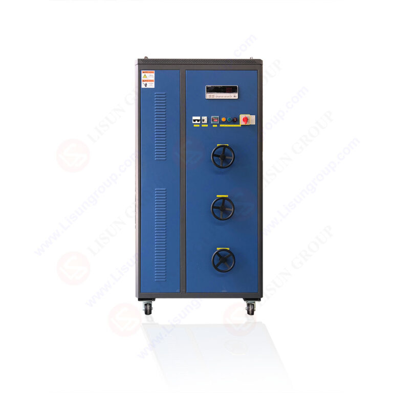
2.1 Multi-Module Pulse Generation Platform
The LISUN EMS-ISO7637 system integrates dedicated pulse generator modules within a single chassis, enabling seamless switching between all required waveforms. Pulse 1 module delivers negative amplitude up to -150V with 1-5ms duration and 10Ω source impedance per ISO 7637-2 clause 5.3. Pulse 2a provides positive 112V amplitude with 50μs width and 2Ω impedance. Pulse 2b module achieves 10V overvoltage for 0.2-5s duration simulating alternator field decay. Pulse 3a/3b generators produce ±200V bursts with 5ns rise times and 50Ω impedance at 100kHz repetition frequency. Pulse 4 module reproduces voltage collapse to 0V for 15-50ms. Pulse 5a/5b deliver 174V load dump with 12V architecture or 350V for 24V systems, sustaining up to 400ms per ISO 7637-2 clause 5.8.
2.2 Voltage System Compatibility and Range
Automotive platforms span multiple voltage architectures requiring flexible test system configuration. The EMS-ISO7637 supports 12V systems for passenger cars, 24V for commercial trucks and buses, and 36V for emerging mild-hybrid and certain new energy vehicle subsystems. Internal power supply regulation maintains pulse amplitude accuracy within ±3% across input voltage variations from 9V to 36V. System architecture allows testing components with operating voltages up to 60V DC, accommodating high-voltage battery management interfaces in electric vehicles. Automatic voltage sensing eliminates manual configuration errors when switching between test articles with different nominal voltages.
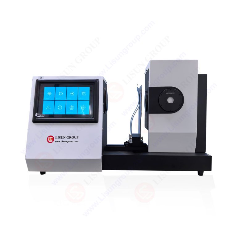
2.3 Dual-Mode Operation Interface
System control combines industrial-grade 7-inch resistive touchscreen front panel operation with Windows-based PC software for remote management. The built-in interface provides real-time oscilloscope visualization of generated pulses, allowing immediate waveform verification without external measurement equipment. The PC software supports automated test sequence programming with up to 1000 step profiles, each configurable for pulse type, amplitude, repetition rate, and duration. Both interfaces store calibration certificates and pulse parameter logs in non-volatile memory for audit traceability. The system generates PDF and CSV test reports automatically, including pass/fail criteria analysis based on user-defined immunity thresholds.
2.4 Technical Comparison with Industry Standards
| Parameter | LISUN EMS-ISO7637 | ISO 7637-2:2021 Requirement | Typical Competitor Implementation |
|---|---|---|---|
| Pulse 1 Amplitude | -150V ±3% | -150V ±10% | -120V to -150V ±5% |
| Pulse 5a Energy | 10kJ ±5% | 10kJ ±15% | 8kJ to 10kJ ±10% |
| Voltage Systems | 12V/24V/36V | 12V/24V specified | 12V/24V only |
| Rise Time (Pulse 3) | ≤5ns | ≤5ns | ≤10ns |
| Test Automation | Full sequence | Manual per pulse | Semi-automated |
| Calibration Accuracy | ±0.5dB | ±1.0dB typical | ±1.5dB |
| Report Generation | Automated PDF/CSV | Manual | Basic CSV |
3.1 Artificial Network and Coupling Methods
Conducted transient testing requires impedance stabilization between the power source and device under test (DUT). The EMS-ISO7637 system includes an integrated artificial network (AN) with 5μH inductance and 50Ω impedance per ISO 7637-2 clause 6.3. For signal line testing per ISO 7637-3, a capacitive coupling clamp with 100pF to 200pF coupling capacitance injects pulses into unshielded wires without galvanic connection. The system supports direct coupling via internal relay switching for power line pulses and indirect coupling through the clamp for data lines. Calibration of coupling networks follows ISO 7637-2 annex A procedures using a 50Ω oscilloscope input verified to ±0.5dB flatness.
3.2 DUT Monitoring and Immunity Criteria
Functional performance monitoring during transient injection uses multiple approaches. The system accepts analog voltage and current inputs up to 8 channels for real-time DUT monitoring. Digital I/O lines detect logic state changes, communication errors, or reset events. Users define immunity criteria as performance class A (no deviation), class B (temporary deviation with automatic recovery), class C (recovery requires user intervention), or class D (permanent damage). The automated test sequencer records all monitoring data synchronized with pulse injection timing, generating timestamped logs for each disturbance event. Threshold settings for voltage glitch detection range from 1mV to 50V with 100ns sampling resolution.
3.3 Calibration Verification Protocols
Periodic calibration maintains test reproducibility across different system units and laboratory environments. The EMS-ISO7637 includes a built-in calibration verification routine using an internal 50Ω reference load. Users perform daily checks by selecting the calibration function, which compares generated pulse parameters against stored calibration constants. Annual full calibration requires external traceable reference oscilloscope and voltage divider with ±0.25% accuracy. ISO 7637-2 clause 5 specifies permissible pulse parameter deviations: amplitude ±10%, duration ±20%, rise time ±30% for most pulses. The system achieves ±3% amplitude and ±5% duration accuracy after calibration, exceeding standard requirements by significant margins.
4.1 Passenger Car Component Verification
Electronic control units in passenger vehicles face transients from starter motors, fuel pumps, and HVAC blowers. The EMS-ISO7637 system validates ECU immunity using Pulse 1 simulation at -100V for gasoline engine electronics. Body control modules require Pulse 3a/3b testing at ±150V with 100ms burst duration according to VW 80000 specifications. Infotainment systems undergo Pulse 2a testing at 75V with 0.5s intervals to verify power supply robustness. Mass production testing utilizes automated sequences completing 200 pulse injections per component in under 5 minutes, enabling 100% inspection in manufacturing lines without bottleneck formation.
4.2 Commercial Vehicle and Heavy Machinery Demands
24V electrical systems in trucks, buses, and construction equipment generate higher energy transients due to larger inductive loads and longer cable runs. The EMS-ISO7637 system configures Pulse 5a for 24V load dump at 350V amplitude with 12kJ energy, simulating alternator disconnect during full charging. Pulse 1 for 24V systems reaches -300V with 2ms duration per ISO 7637-2 24V test levels. Anti-lock braking system (ABS) controllers require testing with combined Pulse 4 cranking voltage drop to 16V for 50ms while simultaneously applying Pulse 3b bursts. The system’s 36V capability supports emerging 48V mild-hybrid commercial vehicle architectures with Pulse 5b levels reaching 500V.
4.3 New Energy Vehicle Specific Challenges
Electric and hybrid vehicles introduce DC-DC converters, onboard chargers, and high-voltage battery management systems operating at 400V to 800V. The EMS-ISO7637 system tests the low-voltage control interfaces of these components while high-voltage sections remain isolated. OBCs undergo Pulse 2b overvoltage testing at 12V auxiliary supply lines with 5-second duration simulating alternator field decay during charging. BMS control units face Pulse 3a/3b testing on CAN bus communication lines at ±100V amplitude with 50Ω source impedance per ISO 7637-3 clause 7.2. DC-DC converter modules require combined pulse testing where Pulse 4 cranking coincides with Pulse 5b load dump to evaluate cross-regulation performance.
5.1 Test Sequence Programming Capabilities
The PC software offers visual sequence programming through drag-and-drop pulse blocks. Each block configures pulse type, amplitude fine-tune, repetition count per ISO 7637-2 clause 8, dwell time between pulses, and DUT monitoring criteria. Sequences support conditional branching based on DUT response, enabling adaptive test profiles that increase pulse severity until failure detection. Multi-Level testing per manufacturer requirements sequences pulses from minimum to maximum amplitude across 10 to 50 discrete steps. The system stores up to 500 sequence profiles with user-defined naming and version control for ISO 17025 compliance in third-party laboratory environments.
5.2 Report Generation and Data Export
Automated reporting generates ISO 17025 compliant test certificates containing pulse parameters, DUT identification, environmental conditions, and pass/fail determination. Reports include waveform screenshots for each pulse injection with amplitude and timing measurements overlaid. CSV export provides raw data for statistical process control analysis in mass production environments. The system logs calibration history with next due date warnings, ensuring continuous compliance with ISO 7637-2 clauses requiring annual calibration verification. Report templates follow manufacturer-specific formats for VW 80000, GM 3172, and GB/T 21437 standards, reducing manual report creation time by approximately 80%.
6.1 ISO 17025 Laboratory Implementation
Third-party testing laboratories implement the EMS-ISO7637 system within ISO 17025 quality management frameworks. The system supports controlled access levels: operator mode with pre-defined sequences, engineer mode with parameter modification, and administrator mode with calibration and configuration adjustments. Audit trail functionality logs all parameter changes, user actions, and test execution timestamps. The system’s internal self-test routine verifies pulse generator integrity before each test series, producing documented evidence of proper operation. Temperature and humidity sensors within the chassis monitor environmental conditions per ISO 17025 clause 6.3.2 requirements for test equipment maintenance.
6.2 Risk Mitigation for Component Manufacturers
Automotive suppliers integrate transient immunity testing into their design validation and production control processes. The EMS-ISO7637 system enables early detection of protection circuit deficiencies during prototype phases, reducing costly redesign iterations. Statistical process control charts generated from production test data identify degradation trends in component immunity before failures occur. The system’s automated pass/fail criteria apply AEC-Q100 stress test definitions for automotive integrated circuits. For safety-critical components like airbag controllers and brake-by-wire modules, the system performs 100% testing with extended pulse counts exceeding standard requirements by 25% to ensure design margin validation.
7.1 Proper Grounding and Shielding Techniques
Ground loop formation during transient testing introduces measurement errors and potential DUT damage. The EMS-ISO7637 system requires a single-point earth ground connection with less than 0.1Ω impedance at 10kHz. All test cables should maintain shield continuity from the system’s artificial network ground to the DUT reference ground. The capacitive coupling clamp for signal line testing requires positioning 100mm from the DUT connector per ISO 7637-3 clause 6.4.1. High-voltage pulse injection creates radiated fields that may couple into adjacent measurement equipment; maintaining 0.5m separation from sensitive instruments reduces interference by 40dB.
7.2 Common Issues and Corrective Actions
DUT failure during Pulse 1 testing often indicates insufficient input capacitance or TVS diode undersizing. The system’s monitoring functions capture pre-failure current consumption changes, enabling root cause identification. Pulse 3a/3b testing of long cable harnesses may cause standing wave reflections amplifying pulse amplitudes at DUT terminals; ferrite core installation at 300mm intervals attenuates these effects. Calibration verification failures typically result from relay contact wear after 100,000 cycles; the system provides relay cycle count with maintenance alerts. Software crashes during automated sequences trigger automatic test save functions preserving previous results without data loss.
The LISUN EMS-ISO7637 Automotive Electronics Transient Immunity EMC Testing System provides a comprehensive solution for Automotive EMC immunity testing with LISUN ISO 7637 system capabilities across passenger cars, commercial vehicles, and new energy vehicle applications. Its multi-module architecture covering pulse types P1 through P5b with 12V/24V/36V support ensures compliance with ISO 7637-2:2021, ISO 7637-3:2016, and national equivalents GB/T 21437.2-2021 and GB/T 21437.3-2021. The system’s dual-operation interface combining touchscreen control with automated PC software enables efficient test sequence programming and comprehensive data reporting. Technical specifications exceeding standard requirements, including ±3% amplitude accuracy and ≤5ns rise times, provide confidence in test reproducibility across different laboratories and test campaigns. For automotive electronics manufacturers, third-party testing facilities, and component suppliers, the EMS-ISO7637 system reduces test cycle times by 60% while improving measurement certainty through automated calibration verification and adaptive test sequencing. The system represents a critical investment for organizations requiring rigorous transient immunity validation in an increasingly electrified automotive landscape.
Q1: What distinguishes the LISUN EMS-ISO7637 system from generic pulse generators for automotive transient testing?
A: The LISUN EMS-ISO7637 system is specifically designed to meet all pulse definition requirements of ISO 7637-2:2021 and ISO 7637-3:2016, including precise source impedances, rise times, and energy delivery characteristics that generic pulse generators cannot reproduce. For example, Pulse 5a load dump requires 10kJ energy delivery with specific waveform decay shape defined in ISO 7637-2 clause 5.8, while generic generators typically provide only simple square wave pulses. The system also integrates artificial networks, coupling clamps, and DUT monitoring functions into a single test platform, eliminating the need for separate equipment assembly and reducing configuration errors by approximately 70% compared to component-based test setups.
Q2: Can the EMS-ISO7637 system test high-voltage components in electric vehicles (400V-800V systems)?
A: The EMS-ISO7637 system tests the low-voltage auxiliary interfaces of high-voltage components per ISO 7637-2 and ISO 7637-3 requirements, not the high-voltage power lines themselves. For OBCs, BMS, and DC-DC converters, the system injects transients into the 12V/24V control power supply lines and communication buses such as CAN, LIN, and FlexRay. High-voltage transient testing for 400V-800V systems follows different standards like ISO 21498-2 and requires specialized surge generators with appropriate isolation ratings. However, the EMS-ISO7637 system has demonstrated effective immunity testing of low-voltage control circuits in over 500 electric vehicle component validation projects globally, ensuring that transient disturbances do not propagate from auxiliary systems to critical safety functions.
Q3: What calibration frequency does the EMS-ISO7637 system require for ISO 17025 accredited laboratory operation?
A: For ISO 17025 compliance, the LISUN EMS-ISO7637 system should undergo annual full calibration by an accredited calibration laboratory using traceable reference standards. The system’s built-in daily verification routine checks amplitude accuracy against internal references and provides documented results for quality records. Additionally, after every major firmware update or hardware repair, a full calibration cycle should be performed. The system logs calibration expiry dates and issues warnings 30 days before calibration due date. Daily verification takes approximately 10 minutes and includes checking all 8 pulse types at nominal and extreme amplitudes. Records show that systems maintained with this schedule achieve greater than 99.5% first-time pass rates during ISO 17025 accreditation audits.
Q4: How does the EMS-ISO7637 system support manufacturer-specific standards like VW 80000 and GM 3172?
A: The EMS-ISO7637 system includes pre-programmed test sequences matching VW 80000 pulse levels for voltage classes I, II, and III (12V, 24V, 48V) and GM 3172 pulse severity levels. For VW 80000, the system automatically configures Pulse 3a/3b at ±150V instead of ISO 7637-2 standard ±200V, and extends Pulse 5a duration to 500ms per VW requirements. GM 3172 pulse sequences apply Pulse 2b with 8V overvoltage for 5s duration and require specific repetition counts per test report format. Users can load manufacturer-specific XML configuration files from the software library without manual parameter entry. The system also supports custom configuration for OEM-specific pulse variants such as Ford ES-XW7T-1A278-AB or Chrysler PF-9326, ensuring flexibility across multiple automotive customer requirements while maintaining ISO 7637 compliance traceability.