









Here is the comprehensive technical article on high-accuracy digital power meters for automotive electronics, structured and written to your exact specifications.
Abstract
High-accuracy AC/DC digital power meters are essential tools for validating the efficiency and power quality of automotive electronics. These instruments, such as the LS2050 series from LISUN, provide precise measurements of voltage, current, power, and harmonic content across a wide frequency range. For R&D and quality control teams in the automotive sector, a high accuracy digital power meter is critical for verifying compliance with standards like EN/IEC61000-3-2 and LM-79, ensuring that power electronics, battery chargers, and infotainment systems meet stringent performance and electromagnetic compatibility (EMC) requirements. This article explores the core technologies, model comparisons, and practical applications of these precision power analyzers in automotive testing environments.
1. Core Technologies in Precision Automotive Power Measurement
1.1 Digital Sampling Waveform Analysis
Modern power meters replace analog multipliers with high-speed analog-to-digital converters (ADCs) that capture the true waveform of current and voltage. This digital sampling method allows for calculation of true RMS, active power, and apparent power regardless of waveform distortion. For automotive electronics, where inverters and switching power supplies generate non-sinusoidal currents, this technology ensures that measurement errors due to harmonic content are minimized. LISUN meters sample at rates sufficient to capture high-frequency switching artifacts up to 100 kHz, providing reliable data for motor drive efficiency analysis.
1.2 Automatic Range Switching
Automotive testing often involves devices that draw inrush currents upon startup, followed by lower steady-state loads. Automatic range switching technology dynamically selects the optimal voltage and current measurement range to maintain accuracy without manual intervention. This feature prevents over-range damage and ensures that low-level measurements remain within the meter’s highest resolution bandwidth. The LS2050C model, for instance, can handle instantaneous overloads up to 1600V and 50A while automatically selecting the appropriate range for the actual operating condition.
1.3 Harmonic Analysis for EMC Pre-Compliance
The ability to perform fast Fourier transform (FFT) on captured waveforms allows these meters to calculate individual harmonic components up to the 50th order using the IEC/CSA method. This is directly relevant to automotive EMC testing, as it provides pre-compliance data for conducted emissions standards. Engineers can identify problematic harmonic orders caused by switching power supplies in electric vehicle (EV) subsystems and take corrective action before formal compliance testing, saving both time and costs.
2. Model Differentiation: LS2050B, LS2050C, and LS2050C-IEC
2.1 Accuracy and Measurement Capabilities
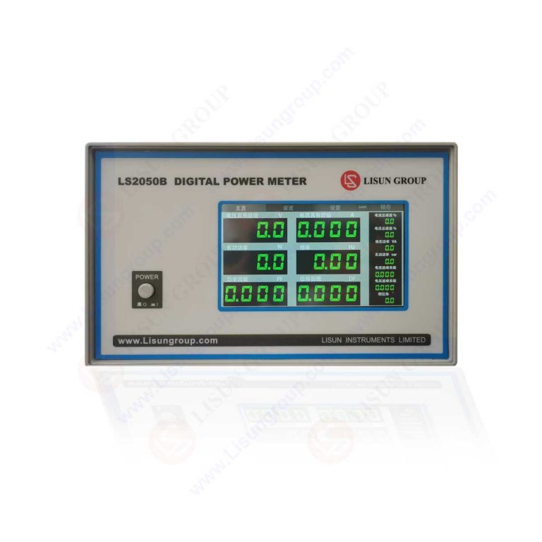
The LISUN LS2050 series offers three tiers of measurement performance tailored to different validation needs. The LS2050B provides standard accuracy suitable for production line testing, while the LS2050C delivers higher precision for R&D validation. The LS2050C-IEC is specifically certified for harmonic compliance testing per EN/IEC61000-3-2, making it the preferred choice for EMC laboratories. All models measure AC and DC signals from 0.5 Hz to 100 kHz, covering the fundamental frequencies and switching harmonics found in automotive power converters.
2.2 Technical Specification Comparison
The following table highlights key differentiators between the models:
| Feature | LS2050B (Standard) | LS2050C (High Accuracy) | LS2050C-IEC (Compliance) |
|---|---|---|---|
| Basic Accuracy (Power) | ±0.2% of reading | ±0.05% of reading | ±0.05% of reading |
| Harmonic Analysis | Up to 20th order | Up to 50th order | Up to 50th order, IEC method |
| Bandwidth | 0.5 Hz – 50 kHz | 0.5 Hz – 100 kHz | 0.5 Hz – 100 kHz |
| Communication Ports | RS232 | RS232 / RS485 | RS232 / RS485 |
| Compliance Certifications | LM-79 / IEC 61010 | LM-79 / IEC 61010 | EN/IEC61000-3-2, CIE |
| Core Application | LED manufacturing, QA | R&D, product validation | EMC pre-compliance |
3. Automotive Electronics Applications
3.1 Validation of Electric Vehicle On-Board Chargers
On-board chargers (OBCs) in electric vehicles convert AC mains power to DC for battery charging, a process inherently rich in low-order harmonics. Using a high accuracy digital power meter to measure input power factor and harmonic currents allows engineers to assess compliance with EN/IEC61000-3-2 Class A limits. The LS2050C-IEC’s built-in harmonic analysis function provides a direct pass/fail indication against these limits. Furthermore, measuring total harmonic distortion (THD) of the input current is critical for optimizing power factor correction (PFC) circuits, directly impacting charging efficiency and grid compatibility.
3.2 Efficiency Testing of DC-DC Converters
Automotive DC-DC converters, used to step down high-voltage battery power for low-voltage accessories (12V infotainment, lighting), require precise efficiency measurements to meet thermal management targets. A key challenge is measuring the low ripple current on the DC output with high accuracy. The LS2050C, with its wide frequency range and high accuracy, can accurately measure both input and output DC power, allowing calculation of conversion efficiency. This data is essential for R&D teams optimizing component selection and switching frequency for maximum energy efficiency.
3.3 Standby Power and Quiescent Current Analysis
Modern vehicles have numerous electronic control units (ECUs) that remain active even when the ignition is off, drawing quiescent current from the battery. High accuracy power meters can resolve these low-power states, measuring down to micro-watt levels. The automatic range switching feature is beneficial here, as it can accurately capture the transition from a high-power active state to a low-power sleep mode without manual range changes. This capability is vital for quality control teams verifying that total vehicle parasitic drain does not exceed battery capacity limits over long parking periods.
4. Compliance Testing and Industry Standards
4.1 EN/IEC61000-3-2 Harmonic Limits
Automotive chargers with a rated power above 75W must meet the harmonic current limits defined in EN/IEC61000-3-2. The LS2050C-IEC model is designed with this standard as its core reference, providing a certified measurement chain for each harmonic order up to the 40th. The meter’s algorithm calculates the moving average of harmonic currents over a 1.5-second window, exactly as required by the testing protocol. This allows EMC lab technicians to perform pre-compliance scans quickly, identifying potential failures related to the 3rd or 5th harmonic, which are common in half-bridge rectifier circuits.
4.2 LM-79 for Solid-State Lighting in Vehicles
Interior and exterior automotive lighting now heavily relies on LED technology. LM-79 is the standard method for measuring the total flux, electrical power, and efficacy of solid-state lighting. A high accuracy digital power meter is central to this test, providing the electrical measurements (voltage, current, power) necessary to complete the photometric report. The LS2050 series, with its support for both AC and DC inputs, can test LED drivers operating from the vehicle’s 12V DC system or from AC inverters, ensuring accurate power readings for lumen-per-watt calculations.
4.3 Safety Standards: IEC 61010 and UL 1989
Electrical safety of test equipment is paramount in a lab environment. The LS2050 series complies with IEC 61010, the safety standard for electrical test and measurement equipment, ensuring protection against electric shock and arc flash. For applications involving connected, high-energy batteries, UL 1989 certification for surge protective devices (often integrated into measurement systems) is relevant. Using a meter that meets these safety standards allows R&D and QA teams to set up tests quickly without fear of instrument failure posing a risk to personnel or the device under test.
5. Hardware Integration and Data Acquisition
5.1 Communication Protocols for Automated Testing
Modern automotive manufacturing requires high-volume testing with automated data logging. The LS2050C and LS2050C-IEC models are equipped with both RS232 and RS485 communication ports, allowing integration into existing automated test equipment (ATE) systems. RS485 supports multi-drop connections, enabling a single computer to control several meters on a test bench simultaneously. This is ideal for end-of-line test stations where an ECU’s power consumption across multiple operating modes must be verified within seconds.
5.2 High Overload Capacity for Robust Testing
A common failure mode in power measurement is damage from transient overvoltage or inrush current. The LS2050 series is designed with a high overload capacity, handling up to 1600V instantaneous peak voltage and 50A instantaneous peak current. This robustness is critical for testing automotive components like motor controllers or solenoids, which can generate large voltage spikes during switching. The meter’s peak hold function can capture these transients for post-mortem analysis, helping engineers diagnose relay arcing or capacitor bank switching issues.
6. Power Factor and Displacement Factor Analysis
6.1 Distinguishing Total Power Factor from Displacement Factor
For nonlinear loads found in automotive electronics, the total power factor (TPF) and displacement factor (DPF) provide different insights. TPF accounts for both the phase shift between voltage and current (DPF) and the distortion power from harmonics. A high accuracy digital power meter calculates both parameters, allowing engineers to diagnose whether a low power factor is caused by a reactive load (phase shift) or by harmonic current drawn by a switching power supply. This distinction is crucial for selecting the correct corrective action, such as adding a capacitor bank versus an active harmonic filter.
6.2 Optimizing PFC in Battery Chargers
Power factor correction (PFC) circuits in EV chargers aim to align the input current with the input voltage, achieving a DPF close to 1.0 and a low THD. During R&D, the power meter provides real-time feedback of DPF and THD as the PFC control loop parameters are adjusted. Using the LS2050C’s wide bandwidth, engineers can see the effect of changing the switching frequency of the boost converter on the input current waveform. The goal is to minimize THD below 10% while maintaining a DPF greater than 0.98, a target easily validated with the meter’s simultaneous display of all parameters.
7. Setting Up a Precision Power Measurement Station
7.1 Best Practices for Voltage and Current Wiring
To achieve the stated accuracy of 0.05%, the wiring configuration must be correct. For low-load testing (e.g., ECUs drawing under 1A), a 4-wire (Kelvin) connection should be used to eliminate the voltage drop across the current-carrying wires. For high-power tests (e.g., motor drives), a 3-phase configuration requires careful attention to phase alignment. The LS2050C meter simplifies this by displaying phase angle information directly. Always use shielded cables for the voltage sense leads to reduce noise pickup, which can add significant error to low-power measurements in an EMC-rich lab environment.
8. Conclusion
The high accuracy digital power meter, exemplified by the LISUN LS2050 series, is an indispensable tool for the automotive electronics industry. From validating the efficiency of high-power EV chargers to measuring the quiescent current of low-power ECUs, these instruments provide the precision needed for both R&D optimization and production-quality assurance. The integration of digital sampling, automatic range switching, and harmonic analysis capabilities directly addresses the complex power quality challenges presented by modern switching converters. Compliance with key industry standards like EN/IEC61000-3-2, LM-79, IEC 61010, and UL 1989 ensures that measurements are both accurate and legally defensible for the target audience of electrical testing and quality control engineers. By selecting the appropriate model, such as the LS2050C for high-accuracy R&D or the LS2050C-IEC for EMC pre-compliance, testing professionals can secure reliable, auditable data.
FAQ (Frequently Asked Questions)
Q1: Why is harmonic analysis important for testing an electric vehicle’s battery charger, and which LS2050 series model is best suited for this task?
A: An electric vehicle charger uses a rectifier and power factor correction (PFC) circuit, which draws a non-sinusoidal current from the mains. Harmonic analysis measures the magnitude of each current harmonic (e.g., 3rd, 5th, 7th order) relative to the fundamental 50/60 Hz frequency. This is critical for EMC compliance because EN/IEC61000-3-2 sets specific limits for each harmonic order. Excess harmonics can cause overheating in distribution transformers and interference with other equipment. The LS2050C-IEC model is best suited for this task. It is specifically certified to perform harmonic analysis according to the IEC/CSA method and provides a direct comparison against the standard’s limit values, making it the ideal choice for EMC pre-compliance and formal testing in an automotive lab.
Q2: How does automatic range switching in a digital power meter improve the efficiency of testing automotive electronic control units (ECUs)?
A: ECUs often operate in multiple power states—drawing high current during active operation (e.g., controlling a fan) and very low current in sleep mode (e.g., maintaining memory). Using a manual range meter would require an engineer to stop the test, select a low range for the sleep mode, and risk an over-range trip when the ECU wakes up. Automatic range switching solves this by continuously monitoring the signal and switching the meter’s internal circuitry to the optimal range. In practice, a single test script can run an ECU through its entire duty cycle, and the meter will automatically log data with the highest possible precision for both the 10mA sleep current and the 5A active current, without interruption or operator intervention.
Q3: In automotive LED lighting testing per LM-79, what specific electrical parameters does the power meter provide, and why must it handle both AC and DC?
A: For LM-79 testing, the electrical power meter must provide the true RMS voltage (Vrms), true RMS current (Irms), and active power (Watts) of the LED driver or luminaire under test. These parameters are used to calculate the luminous efficacy (lumens per watt). The instrument must handle both AC and DC because many automotive LED drivers are designed to operate on the vehicle’s DC system, while others might be tested during the development phase on an AC power source. A quality meter like the LS2050 series provides seamless switching between AC and DC measurement modes, ensuring that the electrical input power is measured accurately regardless of the source, which is vital for a correct photometric report.
Q4: What is the practical difference between the LS2050B and LS2050C for production line testing of small automotive motors?
A: The primary difference lies in accuracy and bandwidth. The LS2050B offers ±0.2% accuracy and a 50 kHz bandwidth, which is sufficient for production line pass/fail testing, where the goal is to ensure the motor operates within a broad power specification. The LS2050C, with its 0.05% accuracy and 100 kHz bandwidth, captures a more detailed power profile, including high-frequency switching losses. For a production line, the LS2050B is often a cost-effective choice. However, during R&D or for low-power, high-efficiency motors where a 1% loss measurement is significant, the superior accuracy and bandwidth of the LS2050C prevent misclassification of units that are close to the specification limits.