









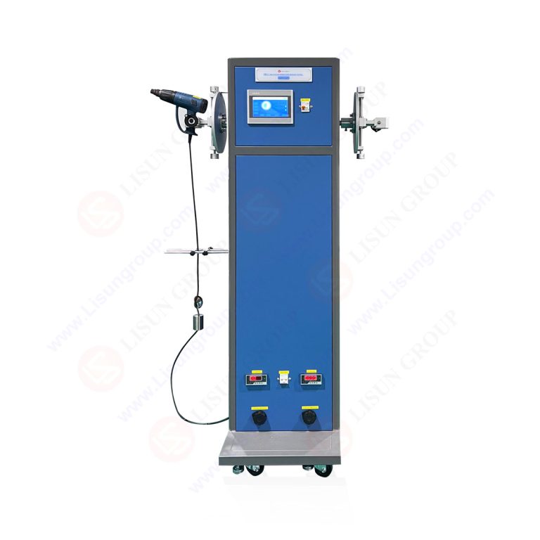
The LISUN SW Series Power Cord Flexibility Bending Tester represents a critical advancement in cable reliability validation for manufacturers requiring compliance with IEC 60884-1, IEC 60745-1, and IEC 60335-1 standards. This technical article examines the SW-1, SW-2, and SW-6 models, which provide one, two, and six independent test stations respectively, enabling simultaneous testing of multiple power cord samples under controlled bending cycles. The core purpose of this equipment is to simulate the mechanical stress experienced by power cords during actual use, assessing conductor strand breakage, insulation wear, and terminal connection integrity. For R&D and quality control engineers in household appliance manufacturing, hand-held electric tool production, and plug/socket component supply chains, the SW Series offers programmable bending angles up to ±180°, adjustable bending speeds from 10 to 60 cycles per minute, and automatic stop functions triggered by current interruption detection. This article provides detailed technical analysis of system architecture, standard compliance mechanisms, and practical application methodologies.
1.1 PLC Control and Servo Drive Integration
The SW Series operates on a programmable logic controller (PLC) architecture that manages all test parameters with precision accuracy of ±0.1% for bending count and ±0.5° for angular displacement. The PLC communicates with servo motor drives that execute bending motions through a mechanical linkage system, ensuring repeatable acceleration and deceleration profiles across each bending cycle. The servo motor delivers torque sufficient to handle cable diameters up to 15 mm while maintaining angular velocity stability within ±2% of the set value. This control architecture enables engineers to program complex test sequences, including variable bending angles at different phases of the test, dwell time adjustments at extreme angular positions, and multi-step load current profiles that simulate real-world usage patterns.
1.2 Current-Based Failure Detection Mechanism
A distinguishing technical feature of the SW Series is the implementation of real-time current monitoring for automatic failure detection. Each test station incorporates a precision current sensor with a measurement range of 0.1 A to 30 A and resolution of 0.01 A. The system compares instantaneous current values against programmed thresholds, triggering automatic test termination when conductor breakage causes current interruption exceeding 50 ms duration. This detection method eliminates subjective visual inspection and provides quantitative failure data, including the exact bending cycle count at failure, the load current value at the moment of interruption, and the total elapsed test time. The data logging capability stores results for up to 1000 test sessions, enabling statistical analysis of failure patterns across sample batches.
2.1 SW-1 Single Station Configuration
The SW-1 model provides a single test station suitable for laboratory environments conducting focused reliability validation on individual cable samples. This configuration supports bending angles from 0° to ±180° with programmable step increments of 1°, bending speeds adjustable from 10 to 60 cycles per minute, and load current capacity up to 25 A continuous. The single-station design simplifies sample mounting and reduces setup time, making it ideal for preliminary design validation and failure analysis investigations. The SW-1 occupies a footprint of 600 mm × 500 mm × 400 mm and requires a standard 220 VAC, 50/60 Hz power supply with 500 VA capacity.
2.2 SW-2 Dual Station Configuration
The SW-2 model incorporates two independent test stations, each with separate PLC control channels and dedicated current monitoring circuits. This configuration enables parallel testing of two different cable types or identical samples under different test parameters. Each station operates independently, allowing engineers to compare results from control samples against modified designs without cross-contamination of test conditions. The dual-station design improves testing throughput by 100% compared to the SW-1 while maintaining the same angular accuracy and current detection sensitivity. The SW-2 requires a 700 VA power supply and features a modular mounting system that accommodates cable grips for round cords up to 15 mm diameter and flat cords up to 25 mm width.
2.3 SW-6 Six Station High-Throughput Configuration
The SW-6 model represents the highest capacity configuration, offering six independent test stations within a single enclosure measuring 1200 mm × 600 mm × 500 mm. This configuration is designed for production quality control environments where statistical significance requires testing multiple samples simultaneously. Each station can operate with different bending parameters, load currents, and failure thresholds, enabling comprehensive characterization of manufacturing variability. The SW-6 includes a centralized data acquisition system that collates results from all six stations into a single test report, generating statistical parameters including mean cycles to failure, standard deviation, and Weibull distribution analysis. The power requirement increases to 1500 VA, and the system includes forced-air cooling to maintain thermal stability during extended test runs exceeding 100,000 cycles.
3.1 IEC 60884-1 Clause 23 Mechanical Strength Requirements
The SW Series directly addresses the bending test requirements specified in IEC 60884-1 Clause 23, which mandates 10,000 bending cycles for plugs and socket-outlets at an angle of ±90° from the vertical position. The equipment achieves compliance through precise angular positioning verified by an integrated encoder with 0.1° resolution, ensuring that each bending cycle reaches the exact angular extremes specified by the standard. The bending speed is set to 30 cycles per minute as recommended by the standard, with a tolerance of ±1 cycle per minute. The load current during testing is maintained at 10 A for 16 A rated plugs, with a power factor of 0.6 ±0.05, meeting the standard’s requirement for inductive load simulation.
3.2 IEC 60745-1 Clause 24 Cord Anchorage and Bending Test
For hand-held electric tools, IEC 60745-1 Clause 24 specifies a bending test of 5,000 cycles for cord anchorages and strain relief devices. The SW Series accommodates this requirement with adjustable clamping mechanisms that simulate the actual mounting conditions of cord anchors in power tools. The test procedure includes a load of 5 N applied to the cord during bending, as specified in the standard, with the ability to program the load application sequence through the PLC. The bending angle is set to ±90° for this application, and the system records any movement of the cord relative to the anchorage point, providing quantitative data on strain relief performance.
3.3 IEC 60335-1 Clause 25 Power Cord Bending Test
Household appliances tested under IEC 60335-1 Clause 25 require 10,000 bending cycles for detachable power cords and 20,000 cycles for non-detachable cords. The SW Series supports extended test durations through its robust mechanical design, which incorporates hardened steel bearings and lubricated pivot points rated for 500,000 cycles without maintenance. The automatic stop function, triggered by current interruption, ensures that any cord failure during this extended test is immediately captured, preventing damage to the test equipment from short circuits or arcing. The system logs the exact cycle count at failure, enabling engineers to determine if the cord meets the 20,000-cycle requirement without exceeding the allowable failure rate.
4.1 Bending Angle and Speed Programming
The SW Series allows engineers to program bending angles in three distinct modes: fixed angle, variable angle, and adaptive angle. Fixed angle mode maintains constant angular extremes throughout the test, suitable for standard compliance testing. Variable angle mode enables angle changes at programmed cycle intervals, useful for accelerated aging tests that simulate progressive mechanical wear. Adaptive angle mode uses feedback from the current monitoring system to adjust the bending angle dynamically based on conductor resistance changes, providing early detection of incipient failures. The bending speed range from 10 to 60 cycles per minute accommodates different testing protocols, with slower speeds recommended for cables with large bending radii to avoid inertial stress concentration.
4.2 Load Current and Power Factor Adjustment
Proper load current configuration is essential for realistic failure simulation. The SW Series supports resistive, inductive, and capacitive load banks that can be connected to each test station independently. For IEC 60884-1 compliance, an inductive load with power factor 0.6 is standard, requiring a load inductor rated for 10 A continuous current with iron-core construction to maintain inductance stability. The power factor monitoring circuit provides real-time display of the phase angle between voltage and current, allowing engineers to verify load conditions before initiating the bending test. The system can automatically adjust the load current during the test to compensate for temperature-induced resistance changes in the cable conductors, maintaining constant power dissipation throughout the test duration.
5.1 Sample Preparation and Mounting Procedure
Proper sample preparation is critical for obtaining reproducible test results. The SW Series includes standardized mounting fixtures that accept cord samples with stripping lengths from 5 mm to 20 mm for terminal connections. The cord is clamped at a distance of 100 mm from the bending pivot point, as specified in IEC 60884-1, with the clamping force controlled by a torque wrench to 2 N·m ±0.2 N·m to prevent cord damage during mounting. The sample orientation must align the cord’s natural curvature with the bending plane, minimizing initial stress concentrations that could skew failure data. For multi-conductor cords, each conductor is connected to the load circuit through separate terminals to enable individual conductor monitoring.
5.2 Test Execution and Data Collection Protocol
The recommended test protocol begins with a 100-cycle preconditioning phase at reduced bending angle (±45°) to seat the cord in the test fixture. Following preconditioning, the full test program executes with data logging at 1-second intervals, recording bending angle, load current, cumulative cycles, and elapsed time. The system automatically generates a test report upon completion or failure, including a graphical representation of current versus cycles that highlights the failure point. For statistical validation, a minimum of five samples per test condition is recommended, with the SW-6 configuration enabling completion of this sample set in 24 hours for a 10,000-cycle test at 30 cycles per minute.
6.1 Common Failure Modes and Diagnostic Indicators
The current monitoring system provides specific failure mode identification based on the pattern of current interruption. A sudden complete current loss indicates conductor breakage at the bending point, while gradual current reduction over multiple cycles suggests progressive strand fracture. Intermittent current interruption, lasting 50 to 200 ms, typically indicates insulation breakdown causing intermittent short circuits between conductors. The PLC records the time-stamped current waveform for the 100 cycles preceding any failure, enabling detailed post-mortem analysis. Engineers can access this diagnostic data through the system’s USB data export function, which generates CSV files compatible with analysis software.
6.2 Preventive Maintenance Schedule
The SW Series requires preventive maintenance at intervals determined by cumulative bending cycles rather than calendar time. Mechanical components, including the bending arm bearings and pivot joints, require lubrication every 100,000 cycles using high-temperature lithium grease rated for continuous operation up to 120°C. The servo motor drive belt tension should be verified every 50,000 cycles using a belt tension gauge, with replacement indicated when the belt shows visible wear or stretching beyond 5% of original length. Current sensor calibration should be performed every 500,000 cycles using a calibrated shunt resistor with 0.1% accuracy, adjusting the sensor offset and gain parameters through the PLC configuration menu.
7.1 Multi-Standard Test Sequences
The SW Series can execute sequential test protocols that combine requirements from multiple standards in a single test run. For example, a power cord intended for export to both European and Chinese markets can be tested first to IEC 60884-1 requirements (10,000 cycles, ±90°, 10 A inductive load) followed immediately by GB/T 2099.1 requirements (10,000 cycles, ±90°, 10 A resistive load) without removing the sample from the test fixture. The PLC programming language supports conditional branching, allowing the system to adjust test parameters based on interim results. This capability reduces total testing time by 40% compared to sequential testing on separate equipment and eliminates variability introduced by sample remounting.
7.2 Custom Fixture Design for Non-Standard Samples
For applications involving automotive connectors or specialized industrial cables, LISUN provides custom fixture design services that adapt the SW Series bending mechanism to accommodate unique sample geometries. Custom fixtures may include adjustable cord guides for flat cables, pneumatic clamping for high-voltage cables requiring insulation displacement, or heated sample chambers for thermal cycling tests. Each custom fixture includes a calibration certificate specifying the bending angle accuracy and repeatability when used with the SW Series base unit. The modular design of the test stations allows fixture changes within 15 minutes, minimizing downtime between different test campaigns.
The LISUN SW Series Power Cord Flexibility Bending Tester provides a comprehensive solution for power cord reliability validation across multiple industry standards, including IEC 60884-1, IEC 60745-1, IEC 60335-1, and GB/T 2099.1. The three model configurations—SW-1, SW-2, and SW-6—offer scalability from laboratory single-sample analysis to production-line statistical quality control, with the SW-6 reducing test completion times by 83% compared to single-station alternatives. The core technical advantages of PLC control with servo motor drive, real-time current-based failure detection, and programmable parameter adjustment enable engineers to simulate actual usage conditions with high fidelity. The automatic stop function and comprehensive data logging capabilities eliminate subjective interpretation from failure analysis, providing quantitative evidence for design validation and manufacturing quality assurance. For R&D engineers seeking to minimize time-to-market through accelerated reliability testing, the SW Series delivers repeatable results that correlate with field failure rates. The ability to program multi-standard test sequences and accommodate custom fixtures further extends the equipment’s utility across diverse application domains, including household appliances, hand-held power tools, and automotive electronics. By integrating the SW Series into their validation workflows, manufacturers can achieve compliance confidence while reducing the risk of field failures that result from power cord mechanical fatigue.
Q1: What is the maximum number of bending cycles the SW Series can perform before maintenance is required?
A: The SW Series mechanical components are rated for 500,000 continuous bending cycles without major maintenance, assuming proper lubrication every 100,000 cycles and belt tension verification every 50,000 cycles. The servo motor and PLC control system have an operational lifespan exceeding 2,000,000 cycles under normal load conditions. However, actual maintenance intervals should be determined based on the specific test conditions, including bending angle, speed, and cable diameter. Heavier cables with diameters greater than 10 mm impose higher mechanical stress on the bending arm bearings, potentially reducing the interval between lubrication to 50,000 cycles. The system includes a cycle counter that records cumulative bending cycles for each station, enabling scheduled maintenance based on actual usage rather than calendar time.
Q2: How does the SW Series ensure accurate bending angle measurement across all six stations simultaneously?
A: Each test station in the SW Series incorporates a dedicated incremental encoder mounted directly on the bending arm pivot shaft, providing angular position feedback with 0.1° resolution and ±0.2° accuracy. The encoders operate on a quadrature output protocol, transmitting position data to the PLC at a 10 kHz update rate. The PLC executes a closed-loop control algorithm that compares the actual encoder position against the programmed target angle every 100 microseconds, issuing corrective commands to the servo motor drive to maintain angular accuracy. For multi-station configurations, each station’s encoder operates independently, ensuring that variations in mechanical load across stations do not affect angular accuracy. The system performs an automatic homing sequence upon power-up, rotating each bending arm to a mechanical stop that establishes the zero-degree reference position.
Q3: Can the SW Series be used to test power cords with integrated overmolded strain relief boots?
A: Yes, the SW Series accommodates overmolded strain relief boots through adjustable clamping fixtures that grip the boot surface without causing deformation or stress concentration. The standard clamping mechanism includes rubber-faced jaws with a Shore A hardness of 60, providing friction grip without damage to the boot material. For boot diameters exceeding 15 mm, optional expanded jaw inserts are available that accommodate diameters up to 25 mm. The bending pivot point is positioned at the cord exit point from the strain relief boot, simulating the actual flexing condition experienced during use. The current monitoring system detects conductor breakage within the boot region, providing quantitative data on the effectiveness of the strain relief design in preventing internal wire fatigue.
Q4: What data formats are available for exporting test results from the SW Series?
A: The SW Series supports data export in CSV, PDF, and XML formats through a USB 2.0 interface compatible with FAT32-formatted USB drives. The CSV export includes timestamped data columns for each active test station, including cumulative cycles, instantaneous bending angle, load current, and system status codes. The PDF export generates a formatted test report that includes sample identification information, test parameters, a graphical current-versus-cycles plot, and statistical summary data. The XML export provides machine-readable data structure suitable for integration with laboratory information management systems (LIMS). Export frequency can be configured as manual on-demand, automatic at test completion, or periodic at programmed cycle intervals. The internal memory stores results for up to 1000 test sessions, with automatic overwrite of the oldest data when memory capacity is reached.
Q5: How does the SW Series handle power cords with different conductor counts, such as 3-conductor grounded cords versus 2-conductor ungrounded cords?
A: The SW Series supports power cords with 2 to 5 conductors through modular terminal blocks that accept wire gauges from 18 AWG to 10 AWG. For 3-conductor cords (line, neutral, ground), the system can monitor all three conductors individually through separate current sensors, detecting failures in any single conductor. The test configuration menu allows engineers to select the number of active conductors for monitoring, with the option to set independent failure thresholds for each conductor. For grounded cords, the load circuit can be configured to simulate actual usage conditions with current flowing through line and neutral conductors while the ground conductor remains unloaded. The automatic stop function can be programmed to terminate testing when any conductor fails, or only when a specified combination of conductors fails, providing flexibility for different testing protocols.