Abstract
This article provides a comprehensive technical guide for IEC 60669-1 Clause 19 testing compliance, focusing on switch durability and breaking capacity verification using the LISUN CZKS-3 series automatic switch durability tester. IEC 60669-1 Clause 19 specifies stringent requirements for mechanical and electrical endurance testing of switches for household and similar fixed electrical installations. The LISUN CZKS-3 series, including variants CZKS-3P, CZKS-3S, and CZKS-3A, offers a PLC-controlled, cylinder-driven solution for automated durability testing. This guide covers test parameter configuration, standard compliance requirements, application scenarios in plug/socket breaking capacity testing and switch life cycle verification, and comparative technical specifications. The article serves electrical component manufacturers, safety testing laboratories, and quality control engineers seeking reliable compliance verification systems for international electrical safety standards.
1.1 Scope and Applicability of Clause 19
IEC 60669-1 Clause 19 governs the mechanical and electrical endurance testing of switches for household and similar fixed electrical installations. This clause applies to switches rated up to 440 V and 63 A, covering both single-pole and multi-pole configurations. The testing protocol evaluates the switch’s ability to withstand repeated operation cycles under specified electrical loads and environmental conditions. Clause 19 testing is mandatory for type approval and certification of switches intended for residential, commercial, and light industrial applications. The standard defines two distinct test sequences: mechanical endurance without electrical load and electrical endurance under rated current and voltage conditions. Both sequences must be completed sequentially without maintenance or adjustment of the switch under test.
1.2 Key Test Parameters and Acceptance Criteria
The IEC 60669-1 Clause 19 test protocol specifies a minimum of 10,000 operating cycles for standard switches, with 20,000 cycles required for switches rated for frequent operation. Each cycle consists of one closing and one opening operation performed at a rate not exceeding 30 operations per minute. The electrical endurance test applies rated voltage at rated current with a power factor of 0.6 ± 0.05 for inductive loads. Acceptance criteria require no electrical breakdown or flashover between live parts, no welding of contacts, and contact resistance remaining within specification limits. The switch must demonstrate satisfactory mechanical function without loosening of components or excessive wear after the complete test sequence. The LISUN CZKS-3 series is designed to precisely control these parameters through programmable logic controller (PLC) systems.
2.1 System Design and Control Architecture
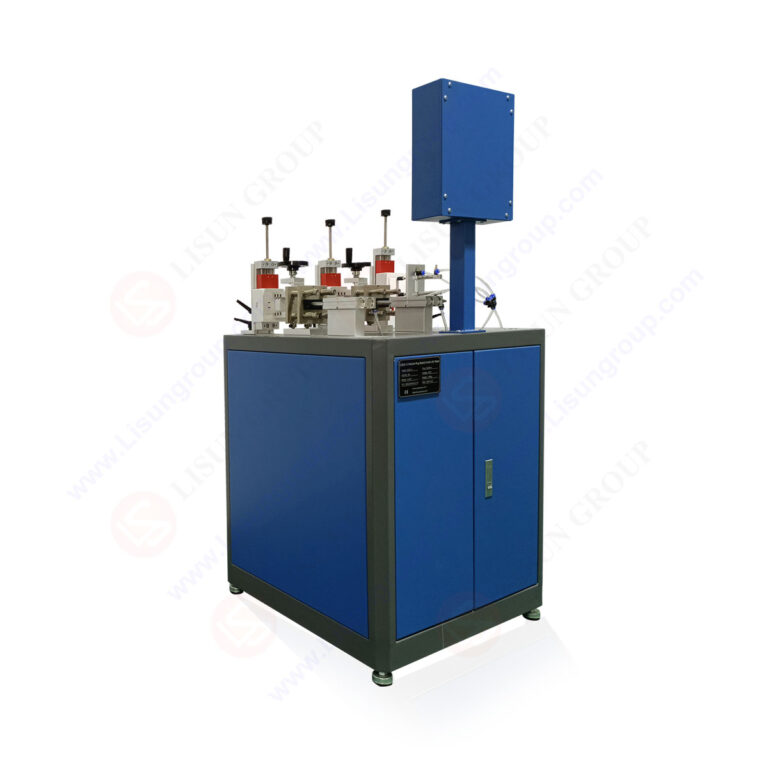
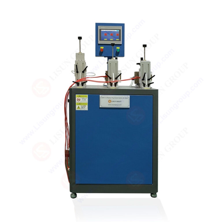
The LISUN CZKS-3 series automatic switch durability tester employs a modular architecture centered on PLC control and cylinder-driven actuation mechanisms. The system integrates a programmable logic controller for sequence control, pneumatic cylinders for mechanical actuation, and precision sensors for monitoring contact status and cycle counting. The CZKS-3 base model supports single-station testing, while the CZKS-3P variant provides multi-station parallel testing capability for increased throughput. The CZKS-3S model incorporates enhanced safety interlocks and emergency stop functions suitable for production line integration. The CZKS-3A variant adds automated data logging and reporting capabilities compliant with ISO/IEC 17025 laboratory requirements. All models feature adjustable test speed settings from 6 to 30 cycles per minute, accommodating the full range specified in IEC 60669-1 Clause 19.
2.2 Technical Specifications and Performance Parameters
The following table presents the comparative technical specifications for the LISUN CZKS-3 series variants:
| Parameter | CZKS-3 | CZKS-3P | CZKS-3S | CZKS-3A |
|---|---|---|---|---|
| Test Stations | 1 | 4 | 2 | 1 |
| Operating Cycles (max) | 99,999 | 99,999 | 99,999 | 999,999 |
| Cycle Rate (cycles/min) | 6-30 | 6-30 | 6-30 | 6-30 |
| Test Voltage Range (V) | 100-440 | 100-440 | 100-440 | 100-440 |
| Test Current Range (A) | 0.1-63 | 0.1-63 | 0.1-63 | 0.1-63 |
| Power Factor Control | Manual | Manual | Auto | Auto |
| Data Logging | None | None | Basic | Advanced |
| Safety Interlocks | Standard | Standard | Enhanced | Enhanced |
The CZKS-3A model provides the most comprehensive data acquisition capabilities, recording contact resistance measurements at predefined intervals and generating compliance reports in standard formats.
3.1 Test Setup and Sample Preparation
Proper test setup begins with securing the switch specimen in the dedicated fixture of the LISUN CZKS-3 series tester. The fixture must accommodate the switch dimensions and provide stable mounting to prevent movement during testing. Electrical connections are made using conductors sized according to the switch’s rated current as specified in IEC 60669-1 Clause 19.2. The test voltage source must be capable of delivering the rated voltage with less than 5% variation, and the load circuit must include adjustable resistive and inductive components to achieve the required power factor. For the LISUN CZKS-3P multi-station setup, each station requires independent load adjustment to ensure all specimens experience identical test conditions. The system’s PLC controller programs the test sequence parameters including cycle count, operating speed, and pause intervals between mechanical and electrical endurance phases.
3.2 Executing the Mechanical and Electrical Endurance Sequences
The mechanical endurance test, performed without electrical load, proceeds for 10,000 cycles at a rate of 30 operations per minute. The CZKS-3 series pneumatic actuators apply a force of 5 N to 50 N depending on the switch type, as specified in IEC 60669-1 Clause 19.3. Following mechanical endurance, the electrical endurance test applies rated current at rated voltage for an additional 10,000 cycles. The LISUN CZKS-3A model continuously monitors contact voltage drop and current waveforms, recording any anomalies exceeding 10% deviation from initial values. The test sequence pauses automatically if contact welding, excessive arcing, or mechanical failure is detected. Upon completion, the system generates a detailed test report including cycle-by-cycle resistance measurements, failure point identification, and pass/fail determination based on the acceptance criteria defined in IEC 60669-1 Clause 19.7.
4.1 Breaking Capacity Verification for Household Connectors
Plug and socket breaking capacity testing, governed by IEC 60884-1 Clause 20, requires verification of the connector’s ability to make and break circuits under specified overload conditions. The LISUN CZKS-3 series effectively adapts to this application through interchangeable actuator heads and adjustable clamping mechanisms. Testing parameters include making and breaking currents up to 1.25 times the rated current at power factors between 0.6 and 0.8. The CZKS-3S model’s enhanced safety features are particularly valuable for breaking capacity tests involving potential arc flash hazards. The system’s precise timing control ensures that each make and break operation occurs within the 1-5 second interval specified in the standard. Data logged during testing identifies contact erosion patterns and arc extinction timing, critical for evaluating connector design compliance.
4.2 Automotive Connector Durability Assessment
Automotive electrical connectors require durability testing under conditions simulating vehicle vibration, temperature cycling, and repetitive mating cycles. While IEC 60669-1 provides the foundational test methodology, the LISUN CZKS-3 series extends to automotive applications through customized test profiles. The CZKS-3P multi-station configuration enables simultaneous testing of multiple connector types, reducing qualification time for automotive component suppliers. Test parameters for automotive connectors typically include 10,000 to 50,000 cycles at currents up to 100 A with voltage levels of 12 V, 24 V, or 48 V DC. The CZKS-3A model’s advanced data logging captures contact resistance trends over the test duration, revealing degradation patterns indicative of fretting corrosion or spring relaxation failures. This data supports predictive reliability modeling for critical automotive electrical systems.
5.1 Rocker Switch and Push-Button Switch Life Cycle Verification
Household rocker switches and push-button switches require durability verification to ensure reliable performance over their expected service life of 20 to 40 years. The LISUN CZKS-3 series accommodates various switch actuator types through interchangeable pneumatic cylinder attachments and adjustable stroke lengths. Testing for rocker switches typically applies a perpendicular actuation force of 2 N to 15 N at the switch’s geometric center. Push-button switches require axial actuation with stroke verification within ±0.5 mm of the specified travel distance. The CZKS-3 base model provides adequate control for standard rocker switches, while the CZKS-3P variant enables parallel testing of multiple switch models for comparative durability analysis. Test results from the CZKS-3A model’s data logging system identify the onset of contact bounce degradation, which correlates with increased arcing and reduced switch life expectancy.
5.2 Dimmer Switch and Electronic Switch Endurance Testing
Dimmer switches and electronic switches present unique challenges due to their semiconductor components and thermal management requirements. The LISUN CZKS-3 series accommodates these devices through adjustable dwell times and reduced cycle rates to prevent thermal buildup. Testing per IEC 60669-1 Clause 19 for electronic switches requires load currents at 100% of rated value with voltage applied for 30 seconds to allow thermal stabilization before cycling begins. The CZKS-3S model’s enhanced safety interlocks monitor case temperature and automatically interrupt testing if thermal limits are exceeded. The CZKS-3A model records temperature data at each cycle interval, providing thermal profiling throughout the test duration. This data validates the switch’s thermal design margin and ensures compliance with the standard’s requirement for no insulation degradation after endurance testing.
6.1 Cross-Reference of Relevant International Standards
The LISUN CZKS-3 series supports compliance testing across multiple international standards, including IEC 60669-1 for switches, IEC 60884-1 for plugs and sockets, and IEC 61058-1 for appliance switches. The following table cross-references key clauses from these standards with the CZKS-3 series testing capabilities:
| Standard | Relevant Clause | Test Requirement | CZKS-3 Series Capability |
|---|---|---|---|
| IEC 60669-1 | Clause 19.2 | Mechanical endurance (10,000 cycles) | Programmable cycle count up to 999,999 |
| IEC 60669-1 | Clause 19.3 | Electrical endurance (rated load) | Current/voltage control up to 63 A/440 V |
| IEC 60884-1 | Clause 20.1 | Breaking capacity (1.25x rated current) | Adjustable load and power factor control |
| IEC 61058-1 | Clause 17 | Mechanical endurance for appliance switches | Force range 5-50 N, stroke adjustable |
| GB/T 2099.1 | Clause 19 | Durability for Chinese national standard | Compatible with GB/T test parameters |
The CZKS-3A model includes pre-programmed test profiles for each standard, reducing configuration time and ensuring consistent compliance with clause-specific requirements. International certification bodies including TÜV, UL, and CCC recognize test data generated by the CZKS-3 series when calibration records and traceability documentation are maintained.
6.2 Calibration and Traceability Requirements
Accurate compliance testing requires periodic calibration of the LISUN CZKS-3 series to maintain traceability to international standards. Calibration parameters include actuation force measurement accuracy within ±2%, cycle timing precision within ±0.1 seconds, and current/voltage measurement accuracy within ±0.5% of reading. The CZKS-3A model incorporates self-diagnostic routines that verify calibration status before each test sequence and generate calibration reminder alerts based on usage hours. Calibration certificates for the CZKS-3 series should reference ISO/IEC 17025 accredited laboratories and document traceability to national measurement standards. The PLC controller’s internal clock must be synchronized annually to ensure accurate cycle timing and data logging timestamps. Proper calibration documentation supports the acceptance of test results by certification bodies and regulatory authorities during product type testing audits.
7.1 Daily Operation and Maintenance Procedures
Daily operation of the LISUN CZKS-3 series begins with visual inspection of pneumatic connections, electrical cabling, and actuator assemblies for signs of wear or damage. The PLC controller should be booted in sequence with the load banks to prevent initialization errors. Operators must verify that the test specimen is correctly mounted and electrically connected before initiating the test sequence. The CZKS-3S model’s enhanced safety interlocks require confirmation that all enclosure panels are secured and emergency stop buttons are functional. Weekly maintenance includes lubricating pneumatic cylinder seals with ISO VG 32 oil and inspecting contact points on the actuator assembly for wear. Monthly calibration verification using a calibrated force gauge and current shunt ensures measurement accuracy remains within specification. The CZKS-3A model’s data logging system generates maintenance reminders based on accumulated cycle count and operating hours.
7.2 Common Fault Conditions and Resolution Strategies
Fault conditions encountered during LISUN CZKS-3 series operation include pneumatic pressure drops below the minimum 4 bar operating threshold, resulting in incomplete actuation cycles. The PLC controller detects this condition and halts testing while displaying the specific error code on the operator interface. Electrical faults such as load bank circuit breaker trips require investigation of the test specimen for short-circuit conditions before resumption. The CZKS-3P multi-station model may experience synchronization errors between stations, typically resolved by recalibrating the station timing parameters in the PLC configuration menu. Contact adhesion failures, detected as increased contact resistance exceeding 100 mΩ, trigger automatic test termination per IEC 60669-1 Clause 19.7 requirements. The CZKS-3A model’s advanced diagnostics log the failure cycle number and contact resistance trend data for root cause analysis. Maintenance personnel should document all fault conditions and resolutions in the equipment log for trend analysis and preventive maintenance planning.
The IEC 60669-1 Clause 19 testing compliance guide demonstrates the critical role of automated durability testing systems in verifying switch and connector reliability for household, commercial, and automotive applications. The LISUN CZKS-3 series, including the CZKS-3, CZKS-3P, CZKS-3S, and CZKS-3A variants, provides comprehensive testing capabilities that address the full spectrum of mechanical and electrical endurance requirements defined in international standards. The PLC-controlled, cylinder-driven architecture ensures precise actuation force, cycle timing, and load management, essential for reproducible test results accepted by certification bodies worldwide. Application scenarios covering plug/socket breaking capacity testing, switch life cycle verification, and automotive connector durability assessment demonstrate the system’s versatility across diverse testing environments. The integrated data logging and reporting features of the CZKS-3A model support compliance documentation requirements for ISO/IEC 17025 accredited laboratories. By implementing the LISUN CZKS-3 series for switch durability testing, manufacturers and testing laboratories achieve consistent compliance with IEC 60669-1 Clause 19, IEC 60884-1, IEC 61058-1, and GB/T 2099.1 standards, ensuring product safety and reliability in critical electrical installations.
Q1: What is the maximum number of test cycles the LISUN CZKS-3A can perform in a single unattended test run?
A: The LISUN CZKS-3A model supports programmable cycle counts up to 999,999 cycles per test run, which is substantially higher than the 10,000 to 20,000 cycles required by IEC 60669-1 Clause 19 for standard switches. At the maximum operating rate of 30 cycles per minute, a 100,000-cycle test completes in approximately 55.6 hours of continuous operation. The system incorporates automatic pause and resume functionality for overnight operation, with safety interlocks that trigger automatic shutdown if contact welding, overcurrent, or mechanical failure is detected. The advanced data logging capability records contact resistance measurements at user-defined intervals (e.g., every 1,000 cycles), enabling detailed degradation trend analysis without requiring operator intervention during the test duration.
Q2: How does the LISUN CZKS-3S model’s enhanced safety system comply with laboratory safety standards?
A: The CZKS-3S model incorporates multiple safety features exceeding the requirements of IEC 61010-1 for electrical test equipment. The enhanced safety system includes dual-channel emergency stop circuits that interrupt both pneumatic supply and electrical power within 100 milliseconds of activation. Transparent polycarbonate safety enclosures with interlock switches prevent access to moving components during operation, with the interlock system rated for 1 million operations. Environmental monitoring includes arc flash detection sensors that trigger immediate shutdown if sustained arcing exceeding 500 ms is detected, protecting both the operator and the test specimen. The safety system’s self-diagnostic function performs a complete check of all safety circuits at system startup and generates a safety status report that can be included in test documentation.
Q3: Can the LISUN CZKS-3 series test switches with non-standard actuator shapes or unusual dimensions?
A: Yes, the CZKS-3 series accommodates non-standard switch geometries through interchangeable actuator accessories and adjustable mounting fixtures. The standard pneumatic cylinder assembly includes a universal actuator head with adjustable stroke length from 5 mm to 50 mm and actuation force control from 5 N to 50 N. For switches with unusual actuator shapes such as rocker switches with curved surfaces or toggle switches with non-perpendicular actuation angles, custom actuator tips can be fabricated from aluminum or acetal copolymer to match the specific geometry. The mounting fixture base plate includes T-slots and adjustable clamping brackets that accommodate switch bodies up to 100 mm × 80 mm × 60 mm. For switches exceeding these dimensions, the CZKS-3S model can be specified with extended mounting hardware and modified actuator assemblies to handle larger enclosures up to 200 mm × 150 mm × 100 mm.
Q4: What data formats are available for test reports generated by the LISUN CZKS-3A model?
A: The CZKS-3A model generates comprehensive test reports in PDF, CSV, and XML formats, supporting integration with laboratory information management systems (LIMS) and quality management software. The PDF report includes a standardized test summary with operator identification, test parameters, cycle count, pass/fail determination, and compliance statements referencing applicable standards including IEC 60669-1 Clause 19. The CSV export provides raw data files containing cycle-by-cycle measurements of contact resistance, actuation force, test current, test voltage, and elapsed time, suitable for detailed statistical analysis using spreadsheet or data visualization software. The XML format complies with the ASTM E2339 standard for electronic data interchange in testing laboratories, enabling automated data transfer to enterprise quality systems. Report templates are customizable through the system’s configuration software, allowing laboratories to add logos, test procedures, and additional compliance documentation as required.
Q5: How does the LISUN CZKS-3P model ensure consistent test conditions across all four test stations?
A: The CZKS-3P model maintains consistent test conditions across all four stations through independent load bank control and synchronized PLC timing. Each station has its own programmable load bank that can be individually set for specific current, voltage, and power factor values, with accuracy maintained within ±1% of setpoint across all stations. The PLC controller synchronizes the actuation timing such that all stations begin and end test cycles simultaneously, with cycle timing variation between stations limited to ±50 milliseconds. The system performs a pre-test verification sequence that checks each station’s electrical and pneumatic parameters before initiating the endurance test, automatically flagging any station that deviates from specified tolerances. During multi-station operation, the CZKS-3P’s data logging system records each station’s performance independently, allowing direct comparison of test results across identical switch specimens under identical test conditions.