Abstract
This comprehensive technical article examines precision compliance solutions for automotive electronics switch testing, focusing on the rigorous validation of mechanical and electrical endurance in switching devices. The primary keyword, automotive electronics switch testing, is integral to ensuring reliability in modern vehicles containing hundreds of switches for infotainment, lighting, window control, and safety systems. The article explores the LISUN CZKS-3 series automated test systems, which provide cylinder-driven actuation, programmable force control, and real-time contact resistance monitoring for compliance with international standards. We analyze testing methodologies for plug/socket breaking capacity, switch durability under load, and failure mode detection. Technical specifications are compared across model variants, and application scenarios in household and automotive contexts are detailed. The content serves design engineers, quality control specialists, and certification laboratories seeking data-driven approaches to switch lifecycle verification.
1.1 The Critical Role of Switch Reliability in Modern Vehicles
Automotive electronics switch testing addresses the unique operational demands placed on switching components in vehicle environments. Unlike household switches that may operate thousands of times, automotive switches must endure hundreds of thousands of cycles under temperature extremes, vibration, and varying electrical loads from 12V to 48V systems. A single failure in a window switch or brake light switch can compromise driver safety and vehicle functionality. The LISUN CZKS-3 series provides the precision actuation and monitoring required to simulate these harsh conditions, enabling manufacturers to identify failure mechanisms such as contact erosion, spring fatigue, and insulation degradation before components enter production.
1.2 Electrical Fatigue Failure Mechanisms
Contact adhesion and material transfer represent primary failure modes detected during automotive electronics switch testing. When switch contacts open under inductive loads, arcing causes metal migration from one contact to another, altering surface geometry and increasing resistance. Testing standards such as IEC 61058-1 for switches and IEC 60669-1 for household switches specify minimum endurance cycles at rated current and voltage. The CZKS-3A model incorporates integrated resistive and inductive load banks to simulate real-world conditions for automotive relays and switches, while the CZKS-3P variant includes pneumatic actuation for high-speed cycling up to 120 operations per minute.
1.3 Measurement Parameters and Pass/Fail Criteria
The cornerstone of effective automotive electronics switch testing lies in defining measurable acceptance criteria. Key parameters monitored during testing include contact resistance (typically 100 MΩ at 500 VDC), dielectric withstand voltage, and mechanical travel distance. The CZKS-3S model features a 0.5% accuracy force sensor that detects 0.01N changes in actuation pressure, crucial for identifying partial contact closure or mechanical binding. Automated systems flag deviations exceeding preset thresholds, enabling statistical process control across production batches.
2.1 IEC and ISO Regulatory Requirements
Comprehensive automotive electronics switch testing must align with multiple international standards. IEC 61058-1:2018 governs general requirements for switches, specifying endurance tests of 10,000 to 100,000 cycles depending on switch category. For automotive applications, ISO 8820-5 addresses fuse and switch coordination in road vehicles, while SAE J560 covers electrical connectors for truck-trailer combinations. The CZKS-3 series test systems are designed to accommodate these standards through programmable test sequences that control actuation speed, dwell time, load application, and monitoring intervals.
2.2 National Standards and Regional Compliance
Manufacturers exporting automotive components must satisfy regional standards including GB/T 2099.1 for Chinese markets, UL 1054 for North America, and EN 60669-1 for European compliance. Each standard imposes unique test conditions: For example, GB/T 2099.1 clause 20 specifies breaking capacity tests at 1.1 times rated voltage, while UL 1054 requires 150% of rated current for overload switching tests. The LISUN CZKS-3 integrates multi-standard test profiles, allowing operators to select parameters automatically based on the target certification. This flexibility reduces setup time and eliminates human error in test parameter configuration during automotive electronics switch testing protocols.
2.3 Harmonization Challenges Across Standards Bodies
Despite international efforts toward harmonization, significant differences persist in test methodologies for automotive electronics switch testing. IEC 60669-1 requires switches to complete 20,000 operations at ambient temperature, while automotive manufacturer specifications (e.g., Ford ES-B6AF-14A054-AA) demand 150,000 cycles with temperature cycling from -40°C to +85°C. The CZKS-3 series addresses these discrepancies through its modular design, supporting integration with environmental chambers and programmable temperature profiles. The system’s PLC-based control architecture enables concurrent execution of multiple test standards on different channels, maximizing laboratory throughput.
3.1 System Architecture and Core Components
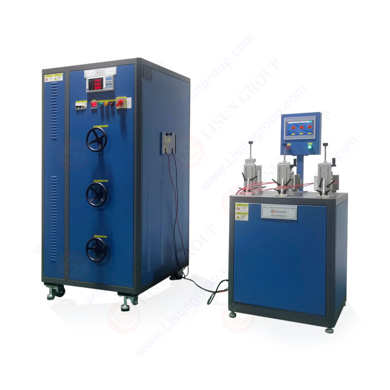
The LISUN CZKS-3 series represents a platform of automated switch durability testers designed for rigorous automotive electronics switch testing. Each system comprises a stepper motor or pneumatic actuator assembly, programmable force controller, contact resistance measurement module with 1µΩ resolution, and a touch-screen HMI for test configuration. The system supports a maximum force range of 0.5N to 50N with adjustable stroke lengths from 5mm to 50mm. Real-time data acquisition at 1000 samples per second captures transient events such as contact bounce and arcing duration, essential for diagnostic analysis.
3.2 Model Variants and Application-Specific Configurations
| Parameter | CZKS-3 | CZKS-3P | CZKS-3S | CZKS-3A |
|---|---|---|---|---|
| Actuation Method | Stepper Motor | Pneumatic | Stepper Motor + Servo | Pneumatic + Load Bank |
| Max Test Speed | 60 cycles/min | 120 cycles/min | 80 cycles/min | 100 cycles/min |
| Force Accuracy | ±1% of full scale | ±2% of full scale | ±0.5% of full scale | ±1% of full scale |
| Load Capacity | Resistive up to 30A | Resistive up to 30A | Resistive up to 30A | Resistive/Inductive up to 50A |
| Measurement Channels | 2 | 4 | 2 | 4 |
| Communication Interface | RS232, USB | RS232, Ethernet | RS485, USB, Ethernet | RS232, Ethernet, Profibus |
The CZKS-3A variant is specifically optimized for automotive electronics switch testing, featuring integrated resistive and inductive load banks that simulate motor, solenoid, and lamp loads common in vehicles. The CZKS-3S provides superior force sensing for membrane switches and tactile feedback components, while the CZKS-3P excels in high-volume production testing of standard rocker and push-button switches.
3.3 Software Integration and Data Management
All CZKS-3 series models include LISUN’s proprietary TestMaster software for automated automotive electronics switch testing workflows. The platform supports multi-step test sequences, statistical process control charts, and automatic report generation in PDF or CSV formats. Data export to MES (Manufacturing Execution Systems) or LIMS (Laboratory Information Management Systems) is accomplished via OPC UA or REST API interfaces. The software maintains an audit trail of all parameter changes and test interruptions, complying with ISO 9001 and ISO 17025 quality management requirements.
4.1 Methodology for Breaking Capacity Verification
Breaking capacity testing evaluates a plug or socket’s ability to interrupt electrical current without sustaining damage or causing safety hazards. For automotive electronics switch testing, this applies to connectors in electric vehicle charging systems, battery disconnect units, and auxiliary power outlets. The test procedure involves inserting the plug into the socket, applying rated current, and withdrawing the plug at a controlled speed while measuring arc duration and contact voltage. The CZKS-3 series controls withdrawal speed between 5mm/s and 100mm/s, matching requirements in IEC 60884-1 clause 20 for socket-outlet breaking capacity.
4.2 Parameter Measurement and Data Analysis
During breaking capacity tests in automotive electronics switch testing, key measurements include peak arc voltage, arc extinction time, and post-test contact resistance. Acceptable arc extinction time for 16A automotive connectors is typically below 10 milliseconds per SAE J560 guidelines. The CZKS-3 system’s high-speed data acquisition captures arc voltage waveforms at 10MHz rate, enabling visualization of arc stability and identifying conditions that could cause contact welding. Statistical analysis across 1000 test cycles reveals trends in contact degradation, allowing manufacturers to optimize material selection and contact geometry.
4.3 Comparative Analysis of Breaking Capacity Performance
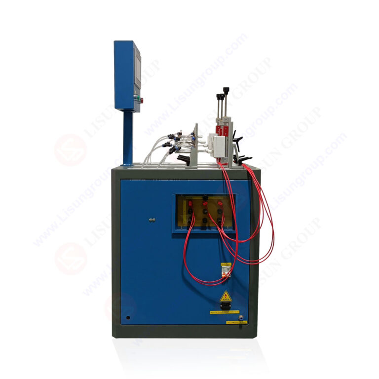
Testing conducted with the CZKS-3A demonstrates that silver-alloy contacts maintain stable breaking capacity for 5000 cycles at 30A resistive load, while copper contacts show a 15% increase in arc duration after only 1000 cycles. The system’s load bank adjusts power factor from 0.6 to 1.0 to simulate inductive loads from motors and solenoids. Results formatted according to IEC 60884-1 Annex B provide certification-ready data for NRTL (Nationally Recognized Testing Laboratory) submissions. This comparative data drives material selection decisions in automotive electronics switch testing for high-reliability applications.
5.1 Mechanical Endurance Under Simulated Conditions
Switch durability testing forms the core of automotive electronics switch testing, validating that components survive the required number of mechanical operations while maintaining electrical integrity. The LISUN CZKS-3 series executes test sequences that combine mechanical actuation with electrical load application according to IEC 61058-1 clause 17. For automotive switches, typical endurance requirements range from 50,000 cycles for interior convenience switches to 500,000 cycles for power window master switches. The system monitors actuation force, return force, and total travel distance on each cycle, flagging deviations that indicate impending failure.
5.2 Environmental Stress Combined Testing
The CZKS-3 series can be configured for combined environmental and electrical stress testing, a critical capability for automotive electronics switch testing. Integration with thermal chambers enables simultaneous temperature cycling (-40°C to +125°C specified in ISO 16750-4) while the switch operates under electrical load. Humidity testing at 95% relative humidity and 85°C per IEC 60068-2-78 reveals moisture ingress failure modes. The system’s PLC control synchronizes temperature ramps with actuation cycles, ensuring switches experience thermal stress during both open and closed contact states.
5.3 Failure Mode Analysis and Root Cause Identification
Automated diagnostics in the CZKS-3 system identify multiple failure modes during automotive electronics switch testing:
- Contact bounce duration exceeding 2ms indicates contact misalignment or pitting
- Actuation force increasing by more than 20% suggests contamination or material fatigue
- Contact resistance >200mΩ flags oxidation or wear-through of plating
- Intermittent open circuits indicate cracked substrate or loose terminals
The system generates Weibull distribution plots for time-to-failure analysis, enabling reliability prediction and warranty risk assessment. Manufacturers use this data to implement design changes before production tooling commitment.
6.1 Multi-Domain Testing Requirements
While automotive electronics switch testing focuses on vehicle components, the same test platforms serve household switch verification across IEC 60669-1 and GB/T 16915.1 standards. Household switches typically require 20,000 to 40,000 mechanical operations at room temperature, significantly fewer than automotive counterparts. However, household applications impose higher current ratings (up to 16A at 250VAC) and specific fire resistance requirements per IEC 60695-2-11. The CZKS-3 series accommodates both domains through interchangeable fixtures and load modules, making it a versatile investment for testing laboratories.
6.2 Certification Testing Protocols
Certification bodies including TÜV Rheinland, UL, and Intertek require witnessed testing or documented evidence of compliance during automotive electronics switch testing. The CZKS-3 system’s test reports include timestamped data, operator identification, and calibration certificates for all measurement channels. The software locks test parameters once a certified protocol is selected, preventing unauthorized modifications. For UL 1054 testing, the system automatically applies 150% rated current for 50 operations, then reduces to rated current for the remaining endurance cycles, matching UL’s overload-condition test methodology.
6.3 Data Integrity and Audit Trail Compliance
The CZKS-3 series maintains an immutable audit log recording all test parameter changes, calibration events, and system errors. Data storage uses redundant flash memory with CRC-32 error checking to prevent corruption. For regulated industries, the system supports 21 CFR Part 11 compliance for electronic records and signatures. During automotive electronics switch testing for tier-1 suppliers, this audit capability satisfies IATF 16949 requirements for test equipment validation and measurement systems analysis (MSA) per AIAG MSA-4 guidelines.
7.1 Multi-Channel Concurrent Testing
Production-scale automotive electronics switch testing demands high throughput without sacrificing measurement accuracy. The CZKS-3P variant supports up to four independent test channels operating simultaneously, each with independent force, speed, and load parameters. This configuration allows testing of four different switch designs or the same switch under four different load conditions concurrently. The system’s distributed processing architecture ensures no data loss during simultaneous high-speed actuation at 120 cycles per minute per channel. Production facilities report 60% reduction in testing cycle time compared to sequential single-channel methods.
7.2 Real-Time Monitoring and Adaptive Control
The CZKS-3 series incorporates adaptive feedback control that adjusts test parameters in response to detected anomalies during automotive electronics switch testing. If contact resistance exceeds a threshold, the system reduces actuation speed to prevent mechanical damage while continuing data collection. Conversely, if switches show consistently low resistance, the system increases test speed to accelerate certification timelines. This dynamic control algorithm, based on fuzzy logic and statistical process limits, optimizes test duration while maintaining data quality for failure analysis.
7.3 Integration with Digital Twin Simulations
Emerging capabilities in the CZKS-3 software platform include data export for digital twin validation of switch designs. Test data from automotive electronics switch testing can be imported into simulation tools such as COMSOL Multiphysics or ANSYS to calibrate finite element models. This integration enables virtual testing of design modifications before physical prototyping, reducing development cycles by 30-40%. The CZKS-3 system’s high-fidelity force and displacement data (0.1mm resolution) validates nonlinear contact mechanics simulations used in modern switch design.
Automotive electronics switch testing demands precision, repeatability, and compliance with multiple international standards. The LISUN CZKS-3 series addresses these requirements through modular, high-accuracy test platforms that validate mechanical endurance, electrical breaking capacity, and environmental resilience. From the CZKS-3 base model to the CZKS-3A with integrated load banks, each variant provides targeted capabilities for specific testing scenarios. The systems’ adherence to IEC 60884-1, IEC 60669-1, IEC 61058-1, and GB/T 2099.1 ensures certification-ready data for global markets. Real-time monitoring of contact resistance, actuation force, and arc characteristics enables early failure detection and root cause analysis, improving switch reliability in critical applications. The comprehensive software platform supports data integrity, audit compliance, and integration with production systems. For manufacturers, testing laboratories, and quality engineers seeking defensible evidence of switch performance, the CZKS-3 series provides the technical foundation for confident product certification and continuous quality improvement.
Q1: What is the difference between the CZKS-3 and CZKS-3P for automotive electronics switch testing?
A: The CZKS-3 uses a stepper motor for precise force-controlled actuation, ideal for delicate switches requiring 0.5N to 50N force with ±1% accuracy. The CZKS-3P uses pneumatic actuation, achieving higher test speeds up to 120 cycles per minute, which is beneficial for high-volume production testing. For automotive electronics switch testing where speed is critical, the CZKS-3P reduces test duration by 50% but sacrifices some force accuracy (±2% versus ±1%). The CZKS-3 is preferred for switches requiring detailed force-displacement analysis, while the CZKS-3P suits standard compliance verification where throughput matters more than granular force data.
Q2: How does the CZKS-3 series comply with IEC 61058-1 for automotive switch endurance testing?
A: The CZKS-3 series implements all test sequences specified in IEC 61058-1 clause 17, including mechanical endurance at no-load, normal load endurance, and overload testing. The system’s programmable parameters cover actuation speed (5-100mm/s), dwell time (0.1-99.9 seconds), and number of cycles (1-999,999). For automotive electronics switch testing, the software includes preloaded profiles matching typical automotive requirements such as 100,000 cycles at 12V/10A with 0.7 power factor. The contact resistance measurement module complies with clause 17.2 measurement requirements using 4-wire Kelvin sensing. The system automatically generates test reports formatted per IEC 61058-1 Annex B, including cycle-by-cycle resistance data and failure event logs.
Q3: Can the CZKS-3 series test switches with non-standard mounting configurations?
A: Yes, the CZKS-3 series accepts custom fixtures for switches with unique mounting geometries. The standard system includes adjustable base plates and actuator adapters accommodating most rocker, toggle, push-button, and slide switches. For automotive electronics switch testing involving irregular shapes or integrated bezels, LISUN offers custom fixture design services using 3D-printed or machined aluminum components. The fixture mounting grid accepts M6 bolts at 25mm spacing, allowing rapid reconfiguration between test runs. The system’s PLC control accommodates multi-axis actuation for switches requiring rotational or compound movement. Maximum fixture envelope is 300mm x 400mm with a maximum component height of 150mm.
Q4: What maintenance is required for the CZKS-3 series to maintain calibration accuracy?
A: Calibration verification for the CZKS-3 series should be performed every 12 months or after 500,000 test cycles, whichever occurs first. Force sensors require calibration using certified dead weights (supplied with the system) traceable to NIST or equivalent national standards. Contact resistance measurement modules use precision decade resistors (1Ω to 10kΩ) for verification. For automotive electronics switch testing laboratories maintaining ISO 17025 accreditation, LISUN provides calibration procedures and uncertainty budgets. Daily operator checks include force sensor zero verification and contact resistance calibration against a known reference. Annual factory recalibration is recommended for the PLC and data acquisition electronics. Consumable parts include pneumatic seals (CZKS-3P and CZKS-3A) requiring replacement every 200,000 cycles.
Q5: How does the CZKS-3A handle inductive load testing for automotive relays and solenoids?
A: The CZKS-3A integrates a programmable inductive load bank that can simulate motor, solenoid, and lamp loads common in automotive systems. The load bank provides power factor adjustment from 0.6 to 1.0 with maximum current of 50A at 48VDC. For automotive electronics switch testing of relays controlling inductive loads, the system employs active snubbing circuits to protect test equipment from back-EMF spikes. The inductive load bank uses precision toroidal cores with selectable inductance values from 10µH to 100mH, allowing simulation of specific vehicle subsystems. The system records arc voltage and current waveforms at 10MHz to analyze contact wear under inductive breaking conditions. Test results include calculated arc energy and contact erosion rates, correlating with IEC 61058-1 Clause 17 requirements for inductive load endurance testing.