Abstract
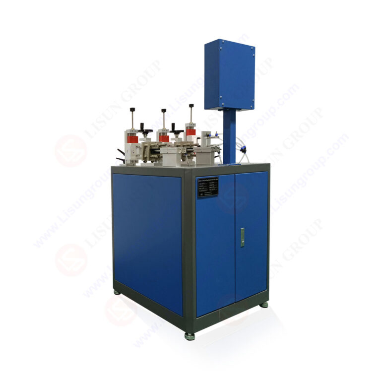
Electrical safety testing labs require precise instrumentation to validate plug, socket, and switch durability against international standards. This article examines the critical role of automated test systems in achieving compliance with IEC 60884-1, IEC 60669-1, and related standards. The LISUN CZKS-3 series serves as the primary reference for mechanical and electrical endurance testing, covering breaking capacity, normal operation, and switch life cycle verification. The article details how the CZKS-3, CZKS-3P, CZKS-3S, and CZKS-3A variants address distinct testing requirements across household and automotive electronics applications. Technical specifications, standard citations, and application scenarios are presented to guide quality control engineers and laboratory managers in selecting appropriate equipment for compliance-driven testing programs.
1.1 Core Testing Requirements for Plugs and Sockets
Electrical safety testing labs must evaluate plug and socket assemblies under conditions that simulate real-world usage stress. The primary parameters include insertion force durability, contact resistance stability, and electrical breaking capacity under load. According to IEC 60884-1 Clause 20, plugs and sockets must withstand 10,000 cycles of mechanical operation without functional degradation. The LISUN CZKS-3 system automates this process using cylinder-driven actuation, precisely controlling insertion depth, angle, and withdrawal speed. Testing engineers must document contact temperature rise, arcing duration, and mechanical wear patterns across the full test cycle.
1.2 Switch Durability Testing Protocols
Switch durability testing follows IEC 60669-1 and IEC 61058-1, which mandate specific numbers of operations under rated electrical loads. For household switches, typical requirements range from 10,000 to 50,000 cycles, depending on the switch category. The CZKS-3S variant is specifically designed for switch life cycle verification, incorporating programmable load banks and real-time resistance monitoring. PLC-controlled sequencing ensures consistent actuation forces and timing, eliminating human variability. Testing labs must also evaluate contact adhesion phenomena, where welded contacts fail to separate under load—a critical safety failure mode addressed by the CZKS-3S’s forced separation detection algorithm.
2.1 System Overview and Model Differentiation
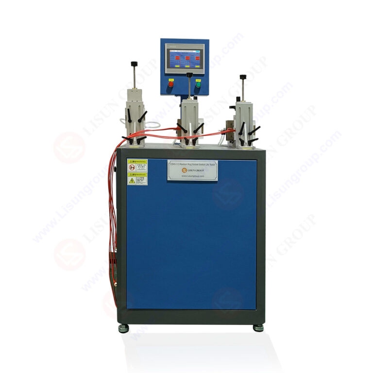
The CZKS-3 series comprises four distinct models tailored to specific testing scenarios. The base CZKS-3 performs plug and socket mechanical endurance tests. The CZKS-3P adds programmable power supply integration for breaking capacity testing under defined voltage and current conditions. The CZKS-3S focuses exclusively on switch durability with enhanced contact monitoring. The CZKS-3A incorporates automotive-grade load simulation for 12V/24V systems. All models share a common PLC control platform, pneumatic actuation system, and data acquisition architecture.
2.2 Key Technical Specifications
| Parameter | CZKS-3 | CZKS-3P | CZKS-3S | CZKS-3A |
|---|---|---|---|---|
| Test Cycles | 0–100,000 | 0–100,000 | 0–200,000 | 0–50,000 |
| Actuation Force Range | 5–150 N | 5–150 N | 1–50 N | 5–200 N |
| Voltage Rating | 250 V AC | 250 V AC / 30 V DC | 250 V AC / 30 V DC | 12–48 V DC |
| Current Capacity | 16 A | 32 A | 16 A | 30 A |
| Contact Resistance Measurement | ±1 mΩ | ±0.5 mΩ | ±1 mΩ | ±1 mΩ |
| Cycle Rate | 10–30 cycles/min | 10–30 cycles/min | 5–60 cycles/min | 10–20 cycles/min |
The table demonstrates how each variant optimizes parameters for specific testing domains. The CZKS-3S achieves the highest cycle count capability, essential for switch durability testing per IEC 60669-1 Clause 19.
3.1 IEC 60884-1 Compliance for Plugs and Sockets
IEC 60884-1 establishes comprehensive requirements for plugs, socket-outlets, and couplers for household and similar purposes. Clause 20 mandates mechanical endurance testing at 10,000 cycles for normal operation, with electrical load applied during the final 1,000 cycles. The CZKS-3 and CZKS-3P directly address these requirements through programmable cycle counters and automatic load application sequencing. Clause 21 covers breaking capacity, requiring the device to interrupt rated current without excessive arcing or contact damage. The CZKS-3P’s integrated power supply and current monitoring capability ensure precise adherence to these test protocols.
3.2 IEC 60669-1 and IEC 61058-1 for Switches
IEC 60669-1 covers switches for household and fixed electrical installations, while IEC 61058-1 addresses switches for appliances. Both standards require endurance testing under rated electrical load, typically 10,000 to 50,000 operations for general-purpose switches. Clause 19 of IEC 60669-1 specifies that switches must complete the test cycle without mechanical failure, contact welding, or insulation breakdown. The CZKS-3S achieves this through precision actuation force control (±1 N accuracy) and real-time contact resistance monitoring. Any resistance increase exceeding 100 mΩ triggers an automatic test halt, allowing immediate failure analysis.
3.3 Automotive Standards and GB/T Compliance
Automotive electrical component testing follows ISO 6722 and GB/T 2099.1 for connectors and switches in vehicle electrical systems. The CZKS-3A variant incorporates low-voltage, high-current test profiles that simulate automotive environments. Vibration resistance, temperature cycling, and corrosion exposure are additional requirements addressed through the system’s programmable environmental chamber interface. The CZKS-3A’s ability to test at 12V/24V with currents up to 30 A makes it suitable for evaluating automotive relay switches, connector systems, and USB charging ports.
4.1 Electrical Breaking Capacity Principles
Breaking capacity testing evaluates a plug, socket, or switch’s ability to safely interrupt electrical current under fault or overload conditions. The test establishes the maximum current the device can interrupt without causing contact welding, excessive arcing, or fire risk. IEC 60884-1 Clause 21 specifies that breaking capacity tests must be conducted at 1.25 times the rated current for household devices. The CZKS-3P performs this test by applying the specified load, then rapidly separating the contacts while measuring arc duration, peak current, and contact voltage drop.
4.2 Automated Breaking Capacity with CZKS-3P
The CZKS-3P automates breaking capacity testing through PLC-controlled sequencing. The system applies the test voltage (typically 250 V AC) and current (up to 32 A), then initiates contact separation at a controlled speed of 100–200 mm/s. Arc extinction time is measured using a high-speed data acquisition module sampling at 10 kHz. Test results are compared against IEC 60884-1 Clause 21 limits: arc duration must not exceed 10 ms, and contact resistance after the test must remain within 150% of the initial value. Any deviation triggers an automatic retest with reduced parameters, ensuring statistical reliability.
5.1 Household Switch Life Cycle Verification
Household switches undergo intensive durability testing to validate long-term reliability. The CZKS-3S applies alternating mechanical and electrical stress cycles, simulating decades of normal use. Typical test profiles include 50,000 mechanical operations without electrical load, followed by 10,000 operations under rated current (10 A at 250 V AC). Contact wear is quantified through periodic resistance measurements every 1,000 cycles. The CZKS-3S’s data logging system generates detailed wear curves, enabling engineers to predict switch failure mechanisms such as spring fatigue, contact material transfer, or housing deformation.
5.2 Automotive Switch Testing with CZKS-3A
Automotive switches face unique challenges including low-voltage operation (12 V), high inrush currents (up to 30 A for motor loads), and exposure to vibration and temperature extremes. The CZKS-3A addresses these requirements through programmable load profiles that simulate inductive motor loads, resistive lighting loads, and capacitive electronic loads. The system performs dielectric withstand tests per ISO 6722, applying 500 V DC between switch terminals and housing while monitoring leakage current. The CZKS-3A’s environmental chamber interface allows synchronized temperature cycling from -40°C to +85°C during durability testing.
6.1 Real-Time Monitoring and Failure Detection
Modern electrical safety testing demands continuous monitoring of critical parameters throughout the test cycle. The CZKS-3 series integrates multiple sensors including load cells for actuation force (±0.5 N accuracy), thermocouples for temperature measurement (±1°C), and high-speed current transducers for arc detection. The PLC executes a real-time failure detection algorithm that identifies contact welding (resistance below 10 mΩ during open state), abnormal arcing (duration exceeding 150% of baseline), and mechanical jamming (force exceeding preset thresholds).
6.2 Automated Report Generation
Test reports are automatically generated in compliance with ISO 17025 laboratory accreditation requirements. The CZKS-3 system produces PDF reports containing summary statistics, cycle-by-cycle resistance plots, and pass/fail determinations referencing specific standard clauses. Reports include raw data exports in CSV format for further statistical analysis. The system supports multiple test templates that can be pre-programmed for standard IEC 60884-1, IEC 60669-1, or GB/T 2099.1 test sequences, reducing setup time by 60% compared to manual testing.
7.1 Matching Test Requirements to System Capabilities
Laboratory managers must evaluate testing requirements against system specifications. For general-purpose plug and socket testing, the base CZKS-3 provides adequate capability for 10,000-cycle mechanical endurance tests. Laboratories conducting breaking capacity verification should select the CZKS-3P for its integrated power supply and high-current measurement capability. Switch manufacturers performing 100,000+ cycle durability tests benefit from the CZKS-3S’s enhanced cycle capacity and force control precision. Automotive component testing is best served by the CZKS-3A, with its low-voltage, high-current test profiles and environmental chamber interface.
7.2 Calibration and Maintenance Considerations
Regular calibration ensures test results remain traceable to national standards. The CZKS-3 series supports automated calibration routines for force sensors, current transducers, and resistance measurement circuits. Recommended calibration intervals are 12 months for force and temperature sensors, and 6 months for current and voltage measurements. The system’s modular design allows individual component replacement without full system recalibration. Spare parts including pneumatic cylinders, solenoid valves, and contact assemblies are readily available from LISUN, minimizing downtime.
Electrical safety testing laboratories operating in compliance with IEC 60884-1, IEC 60669-1, IEC 61058-1, and GB/T 2099.1 require automated test systems that deliver precision, repeatability, and data integrity. The LISUN CZKS-3 series provides a comprehensive solution for plug and socket breaking capacity testing, switch durability verification, and automotive component evaluation. The four model variants—CZKS-3, CZKS-3P, CZKS-3S, and CZKS-3A—address distinct testing domains while sharing a common architecture of PLC control, pneumatic actuation, and real-time monitoring. Key technical advantages include actuation force accuracy within ±1 N, current measurement precision to 0.5 mΩ, and automated failure detection algorithms that identify contact welding and abnormal arcing. Laboratories implementing the CZKS-3 series benefit from reduced test cycle times, standardized reporting compliant with ISO 17025 requirements, and traceable calibration protocols. For quality control engineers and laboratory managers, the CZKS-3 series represents a technically robust investment in electrical safety compliance testing, ensuring that plugs, sockets, and switches meet international durability and safety standards before reaching the market.
Q1: How does the CZKS-3 series differentiate between normal contact wear and failure modes such as contact welding?
A: The CZKS-3 series employs a dual-threshold failure detection algorithm. Normal contact wear is characterized by gradual resistance increase (typically 10–30 mΩ over 10,000 cycles). Contact welding, however, produces a sudden resistance drop to below 10 mΩ during the open state, indicating that contacts remain physically bonded. The system measures resistance at each cycle’s open and closed states, comparing values against adaptive baselines updated every 100 cycles. When the open-state resistance falls below 10 mΩ for three consecutive cycles, the test is automatically halted, and a “Contact Welding” failure code is logged. This discrimination prevents unnecessary rejection of worn-but-functional devices while ensuring safety-critical welding failures are reliably detected.
Q2: Can the CZKS-3P perform breaking capacity tests on three-phase plugs and sockets?
A: Yes, the CZKS-3P can be configured for single-phase or three-phase breaking capacity testing. For three-phase applications, the system uses a three-channel current measurement module and synchronized contact separation across all phases. The PLC ensures that all three poles open within 1 ms of each other, simulating real-world three-phase interruption. Test profiles per IEC 60884-1 Clause 21 for three-phase devices apply the same 1.25× rated current per phase, with arc extinction time measured individually. The CZKS-3P’s maximum current capacity of 32 A per channel supports testing of three-phase plugs rated up to 20 A per pole. The system automatically calculates and reports three-phase power parameters including total harmonic distortion and power factor.
Q3: What maintenance procedures are required to ensure consistent test results over extended operation?
A: The CZKS-3 series requires three maintenance tiers. Daily checks include verifying pneumatic pressure (4–6 bar), inspecting actuation cylinders for seal leaks, and cleaning contact test specimens using isopropyl alcohol to remove oxidation. Monthly maintenance involves calibrating force sensors using a certified load cell reference (0.1% accuracy), cleaning pneumatic solenoid valves, and backing up test data to external storage. Annual maintenance includes full system calibration by a LISUN-authorized technician, replacement of pneumatic seals, and lubrication of linear guide rails. The system’s diagnostic software provides maintenance reminders based on cycle count, typically prompting service every 50,000 cycles. All calibration records are stored within the system’s internal database for ISO 17025 audit traceability.
Q4: How does the CZKS-3S achieve 200,000-cycle durability testing without mechanical wear affecting results?
A: The CZKS-3S incorporates three design features to maintain mechanical precision over extended testing. First, the linear actuator uses a recirculating ball screw drive instead of a standard pneumatic cylinder, achieving 0.1 mm position repeatability over 200,000 cycles. Second, the actuation force sensor is mounted directly on the moving carriage, compensating for any wear in the drive mechanism through closed-loop force control. Third, the system automatically adjusts actuation stroke length every 10,000 cycles to account for contact erosion, maintaining consistent over-travel distance. The PLC logs force, position, and velocity at each cycle, generating trends that identify mechanical degradation before it affects test validity. This design ensures that the 200,000-cycle test result reflects switch durability rather than test system wear.
Q5: What are the benefits of integrating the CZKS-3A with an environmental chamber for automotive component testing?
A: Integrating the CZKS-3A with an environmental chamber enables combined temperature, humidity, and electrical cycling tests that simulate real-world automotive conditions. The CZKS-3A’s control software communicates with the chamber via RS-485 or Ethernet, synchronizing temperature profiles (e.g., -40°C to +125°C ramp cycles) with electrical load sequences. This integration reveals failure modes that isolated testing cannot detect, such as contact material expansion causing intermittent connection at high temperature, or condensation-induced corrosion at low temperature. The system automatically pauses electrical testing during temperature transitions to prevent thermal shock artifacts. Test reports include time-stamped temperature, humidity, and electrical parameter data, enabling correlation analysis that identifies the specific environmental stress causing failure. This capability is critical for meeting ISO 6722 and automotive OEM-specific durability requirements.