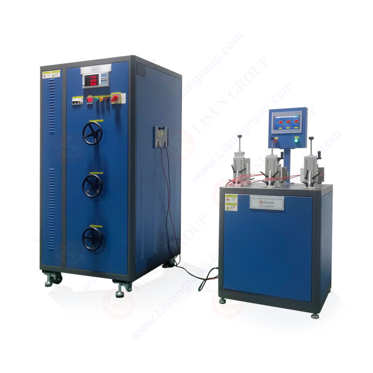
This technical article provides a comprehensive analysis of the PLC-Controlled Switch Life Tester for Precise Durability Testing, focusing on the LISUN CZKS-3 series as a critical tool for electrical component manufacturers and safety testing laboratories. The primary keyword “PLC-Controlled Switch Life Tester” refers to an automated test system designed to evaluate the mechanical and electrical endurance of switches, plugs, sockets, and connectors under repeatable, programmable conditions. The article examines the system architecture, including PLC-based logic control, pneumatic actuation mechanisms, and real-time monitoring capabilities. Detailed technical specifications of the CZKS-3, CZKS-3P, CZKS-3S, and CZKS-3A models are compared, alongside compliance frameworks such as IEC 60884-1, IEC 60669-1, IEC 61058-1, and GB/T 2099.1. Application scenarios span household electrical durability testing, automotive switch verification, and breaking capacity assessment for plugs and sockets. The article concludes by reinforcing how this PLC-Controlled Switch Life Tester ensures reproducible, data-driven quality assurance for component manufacturers seeking regulatory compliance.
1.1 Principles of Automated Durability Evaluation
The PLC-Controlled Switch Life Tester operates on a foundation of programmable logic control combined with pneumatic or electromechanical actuation. A programmable logic controller (PLC) serves as the central processing unit, executing test sequences that simulate repeated user interactions with electrical switches, plugs, or sockets. The system applies mechanical force through cylinder-driven actuators, engaging and disengaging contacts at user-defined intervals. Each actuation cycle is monitored for electrical continuity, contact resistance, and mechanical displacement. The PLC-Controlled Switch Life Tester records failure events such as contact welding, insulation breakdown, or mechanical jamming, enabling engineers to quantify the mean cycles to failure (MCTF). This automated approach eliminates human variability, ensuring that test results are statistically valid and reproducible across different laboratories and production batches.
1.2 Core Components and System Architecture
A typical PLC-Controlled Switch Life Tester integrates several key subsystems: the PLC controller with touchscreen HMI, pneumatic cylinders with pressure regulation, power supply units for load simulation, and data acquisition modules. The LISUN CZKS-3 series implements a modular design where each test station operates independently. The PLC manages test parameters including actuation speed, dwell time, and load current. Pneumatic cylinders provide consistent force ranging from 5N to 50N, adjustable via proportional pressure valves. The system includes safety interlocks that halt operation if contact resistance exceeds predefined thresholds, preventing catastrophic failure of test samples. Real-time data logging captures every cycle’s electrical parameters, which are exported as CSV files for statistical process control analysis. The architecture supports simultaneous testing of multiple samples, increasing throughput for accelerated life testing protocols.
1.3 Comparison with Manual and Semi-Automated Alternatives
Manual switch life testing relies on technicians physically operating test samples, introducing significant variability in actuation force, speed, and angle. Semi-automated systems reduce some variability but still require operator intervention for data logging. The PLC-Controlled Switch Life Tester achieves full automation, with the LISUN CZKS-3 series capable of executing over 1,000,000 cycles without human intervention. Manual testing typically achieves 10-20 cycles per minute, while the CZKS-3 systems operate at 30-60 cycles per minute depending on sample geometry. More critically, automated systems maintain consistent actuation parameters within ±2% tolerance, compared to ±15% variation in manual testing. This precision enables detection of subtle degradation patterns in contact materials, arcing behavior, and spring fatigue that manual methods would miss due to statistical noise.
2.1 Model Differentiation and Capabilities
The LISUN CZKS-3 series encompasses four distinct models tailored to specific testing requirements. The CZKS-3 base model supports standard switch and socket durability tests with up to 4 independent test stations. The CZKS-3P incorporates enhanced pneumatic control for high-frequency cycling up to 120 cycles per minute, suitable for micro-switch and tact switch testing. The CZKS-3S includes a specialized sample fixture for sliding switches and rocker switches with non-standard actuation angles. The CZKS-3A adds an integrated AC/DC power supply for breaking capacity testing under load conditions up to 250V/16A. All models share a common PLC platform, enabling test program portability between units. The following table provides a numerical comparison of key specifications:
| Parameter | CZKS-3 | CZKS-3P | CZKS-3S | CZKS-3A |
|---|---|---|---|---|
| Number of Test Stations | 4 | 6 | 4 | 4 |
| Max Cycles per Minute | 60 | 120 | 60 | 45 |
| Actuation Force Range (N) | 5-30 | 5-50 | 5-30 | 5-30 |
| Load Current Capacity (A) | 10 | 10 | 10 | 16 |
| Voltage Rating (V AC/DC) | 250 | 250 | 250 | 250 |
| Contact Resistance Threshold (mΩ) | 100 | 100 | 100 | 100 |
| Programmable Dwell Time (s) | 0.1-99.9 | 0.1-99.9 | 0.1-99.9 | 0.1-99.9 |
2.2 Compliance with International Testing Standards
The CZKS-3 series is designed to meet key clauses of international electrical safety standards. For IEC 60884-1 (Plugs and socket-outlets for household and similar purposes), the tester addresses Clause 20 on mechanical endurance and Clause 21 on breaking capacity. IEC 60669-1 (Switches for household and similar fixed electrical installations) requirements for mechanical endurance (Clause 19) and electrical endurance (Clause 20) are fully supported. IEC 61058-1 (Switches for appliances) testing for normal operation (Clause 15) and abnormal operation (Clause 16) can be programmed into the PLC. For the Chinese GB/T 2099.1 standard, which aligns with IEC 60884-1, the CZKS-3A variant provides the necessary load current and voltage levels. The PLC-Controlled Switch Life Tester’s data logging capabilities satisfy the documentation requirements for Type Testing and routine verification under these standards.
2.3 Precision Actuation and Measurement Systems
Each test station in the PLC-Controlled Switch Life Tester employs a linear actuator with position feedback via a linear variable differential transformer (LVDT) or encoder. Positioning accuracy is ±0.1mm, critical for switch types with short snap-action travel distances. The pneumatic system uses proportional pressure regulators to maintain force within ±1% of the setpoint over the entire test duration. Contact resistance is measured using a four-wire Kelvin method, with resolution of 0.1mΩ. The PLC executes a pass/fail decision at every cycle, comparing measured resistance against the user-defined threshold. For breaking capacity tests, the CZKS-3A integrates a resistive-inductive load bank that simulates real-world electrical loads. The system captures arc duration and energy using high-speed sampling at 100 kHz, providing data for contact material optimization.
3.1 Household Electrical Component Verification
The primary application for the PLC-Controlled Switch Life Tester is in verifying the durability of household electrical components. Light switches, dimmer controls, and socket outlets undergo accelerated life testing per IEC 60669-1, which requires 20,000 to 40,000 mechanical cycles depending on switch type. The LISUN CZKS-3 series tests wall switches with toggle, rocker, and push-button mechanisms. For socket outlets, IEC 60884-1 requires 5,000 insertion/withdrawal cycles for normal use, with the plug inserted and withdrawn at a rate of 10 cycles per minute. The CZKS-3 and CZKS-3S models include specialized grippers that mimic human finger geometry, ensuring realistic actuation. Testing under load conditions (e.g., 10A at 250V) evaluates contact temperature rise, arcing damage, and insulator degradation over the product’s rated life.
3.2 Automotive Switch and Connector Durability
Automotive electronics require extreme durability due to vibration, temperature cycling, and high inrush currents. The PLC-Controlled Switch Life Tester adapted for automotive components tests window switches, door lock actuators, and ignition switches to 100,000 to 500,000 cycles. The CZKS-3P variant’s high-speed capability is particularly useful for testing micro-switches in seat adjustment mechanisms and steering column controls. Automotive connectors are tested for insertion/withdrawal forces and contact resistance stability over 10,000 cycles. The system can be programmed with temperature compensation factors or integrated with an environmental chamber for combined temperature-humidity-vibration testing. Data from these tests informs design decisions for contact plating materials (gold, silver, tin) and spring geometries.
3.3 Breaking Capacity and Short-Circuit Testing
Breaking capacity testing evaluates a switch’s ability to interrupt current flow under fault conditions. The CZKS-3A variant includes a programmable load bank that can simulate resistive, inductive, and capacitive loads up to 16A at 250V AC or 30V DC. The PLC-Controlled Switch Life Tester executes a make-and-break sequence at specific points in the AC waveform to maximize arc energy, per IEC 61058-1 Clause 16. The system measures arc extinction time, contact bounce duration, and post-test insulation resistance. This testing is critical for switches used in motor control circuits, where inductive loads generate high arc voltages. The automated system ensures that each breaking test occurs at the same electrical angle, providing reproducible arc energy measurements. Results are compared against acceptance criteria such as no welding of contacts, no insulation breakdown, and arc duration under 10ms.
4.1 Test Program Development and Parameter Setting
Configuring the PLC-Controlled Switch Life Tester begins with defining the test program on the touchscreen HMI. Operators select the test standard (e.g., IEC 60669-1) and the model automatically populates parameter ranges. Key parameters include number of cycles, actuation speed, dwell time (open and closed positions), force profile, and load current. The PLC supports up to 50 stored programs, each containing multiple test phases. For example, a switch test might include 10,000 dry cycles (no load) followed by 10,000 cycles under rated load. The CZKS-3 series allows force profiling where initial cycles use higher force to simulate aging of lubricants, followed by reduced force for steady-state operation. The system includes a calibration routine that verifies actuator force and position against certified reference sensors before each test run.
4.2 Real-Time Monitoring and Failure Detection
During operation, the PLC-Controlled Switch Life Tester continuously monitors multiple parameters. Contact resistance is measured between 10ms and 100ms after contact closure, ensuring stable readings. If resistance exceeds the threshold (typically 100mΩ for new contacts, with drift allowance), the system logs the cycle number and initiates a retest. Three consecutive failures trigger a test abort and alarm. Force sensors on each actuator detect mechanical jamming or sample deformation. The system also monitors pneumatic pressure, motor current, and ambient temperature. Live data is displayed on the HMI in graphical format, showing resistance trends, force profiles, and cycle count. This real-time visibility enables operators to observe degradation patterns, such as gradual resistance increase indicating contact wear or sudden spikes indicating particle contamination.
4.3 Data Export and Analysis
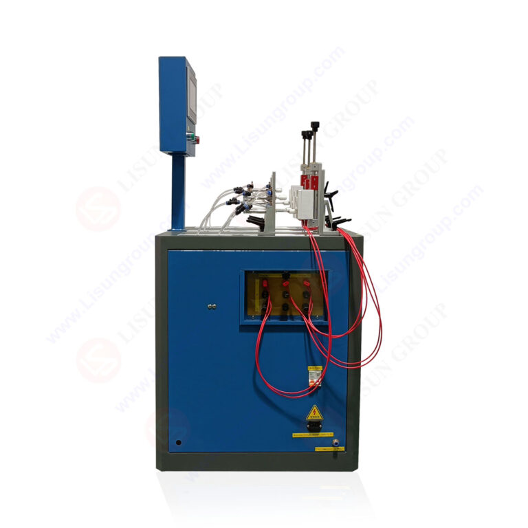
Each completed test generates a comprehensive report including cycle-by-cycle data, statistical summaries, and failure event logs. The PLC-Controlled Switch Life Tester exports data in CSV and PDF formats. Statistical outputs include mean cycles to failure, Weibull distribution parameters, and confidence intervals. For batch testing of multiple samples, the system calculates Cp and Cpk process capability indices. Engineers can overlay data from multiple test runs to compare design iterations or production lots. The LISUN CZKS-3 series supports network connectivity for integration with laboratory information management systems (LIMS), enabling automated data archiving and audit trail compliance. This data infrastructure supports root cause analysis when field failures occur, linking laboratory test results to actual product performance.
5.1 Actuator Selection and Force Control
The choice of pneumatic versus electromechanical actuators in the PLC-Controlled Switch Life Tester depends on test requirements. Pneumatic cylinders provide high force output with smooth motion profiles, ideal for larger switches and sockets. The CZKS-3 and CZKS-3P use Festo or SMC cylinders with magnetic position sensors. Force control is achieved through proportional pressure regulators that adjust air pressure based on feedback from load cells. For switches requiring precise force control (e.g., micro-switches with 1N operating force), the system can use voice coil actuators with ±0.01N accuracy. The actuator mounting system allows quick-change tooling for different switch geometries, reducing setup time between test campaigns. All actuators are rated for 10 million cycles before maintenance, with sealed bearings to prevent contamination from switch debris.
5.2 Electrical Load Simulation and Measurement
The load simulation subsystem in the PLC-Controlled Switch Life Tester must accurately represent real-world electrical conditions. The CZKS-3A includes a resistive-inductive load bank with programmable power factor from 0.6 to 1.0. The load bank uses high-power wire-wound resistors and iron-core inductors, capable of dissipating up to 4kW continuously. For DC testing, the system includes a low-ripple power supply with adjustable voltage up to 30V and current up to 20A. Current measurement uses Hall-effect sensors with 0.5% accuracy, while voltage measurement uses isolated differential probes. The data acquisition system samples at 100 kHz to capture arc transients and inrush current peaks. This high-speed measurement capability is essential for evaluating switch bounce characteristics and arc extinction behavior per IEC 61058-1.
5.3 Safety Systems and Interlocks
Given the electrical and mechanical hazards inherent in life testing, the PLC-Controlled Switch Life Tester incorporates multiple safety systems. Emergency stop buttons are positioned at each test station and on the main control panel. The PLC monitors all safety interlocks, including door switches, cover interlocks, and overcurrent protection. If a contact welding event occurs (where the switch fails to open), the system immediately removes load power and retracts the actuator. The pneumatic system includes pressure relief valves and air filters to prevent cylinder over-travel. For high-energy breaking capacity tests, the test chamber is constructed with arc-resistant materials and includes ventilation for arc byproducts. All safety circuits are hardwired independently of the PLC logic, ensuring fail-safe operation even in the event of controller failure.
6.1 Traceability and Audit Trail Compliance
The PLC-Controlled Switch Life Tester supports full traceability for ISO 17025 and ISO 9001 compliance. Test programs are stored with version control, including timestamps and operator identification. Each test result file includes the serial numbers of the test equipment, calibrated sensors, and test samples. The system records any parameter changes made during the test, along with the reason for the change. This audit trail is stored in an encrypted database that cannot be modified after the test concludes. For regulatory audits, the LISUN CZKS-3 series can generate summary reports that include equipment calibration certificates, test method references, and measurement uncertainty budgets. This level of documentation satisfies the requirements of notified bodies for product certification under IECEE CB Scheme.
6.2 Statistical Process Control Integration
Beyond simple pass/fail testing, the PLC-Controlled Switch Life Tester enables statistical process control (SPC) monitoring of production quality. When testing samples from a production line, the system calculates control limits for key parameters such as initial contact resistance, insertion force, and electrical endurance. Trends in these parameters can indicate tooling wear, material variability, or process drift before failures occur. The CZKS-3 series includes built-in X-bar and R chart generation, with automatic flagging of out-of-control conditions. Engineers can set up automated notifications when process capability indices fall below acceptable thresholds. This proactive approach reduces scrap rates and field failures, as production issues are identified and corrected in real-time rather than through retrospective batch testing.
6.3 Inter-Laboratory Correlation Studies
For manufacturers with multiple testing facilities, the PLC-Controlled Switch Life Tester facilitates inter-laboratory correlation studies. The LISUN CZKS-3 series uses identical PLC programs and sensor calibration procedures across all models, ensuring that test results are comparable between sites. Reference samples with known durability characteristics are tested periodically to verify system alignment. Statistical analysis of inter-laboratory results uses ANOVA to identify any systematic differences. The system’s data format supports easy consolidation of results from multiple testers into a central database. This capability is essential for global manufacturers who need to qualify products in one location and have those qualifications recognized at other facilities or by regulatory bodies.
7.1 Incorporating IoT and Remote Monitoring
The next generation of PLC-Controlled Switch Life Tester systems is moving toward Internet of Things (IoT) connectivity. The CZKS-3 series can be equipped with Ethernet and Wi-Fi modules for remote monitoring and control. Engineers can access real-time test data from mobile devices, receive alerts for failure events, and modify test parameters without being physically present. Cloud-based data storage enables historical trend analysis across multiple test campaigns and equipment installations. Machine learning algorithms applied to historical test data can predict remaining useful life of test samples, optimizing test termination points. Remote diagnostics allow LISUN technical support to troubleshoot issues without site visits, reducing downtime. These capabilities align with Industry 4.0 initiatives for smart manufacturing and predictive maintenance.
7.2 Multi-Axis and Multi-Mode Testing
Future testing requirements demand more complex actuation patterns than simple linear motion. The PLC-Controlled Switch Life Tester is evolving to support multi-axis testing, where switches are actuated from different angles or with rotational motion. This is particularly relevant for automotive joystick controls, rotary encoders, and multi-function switches. The CZKS-3S variant’s modular fixturing already accommodates non-standard motion profiles, and future releases will include servo-driven rotary actuators. Multi-mode testing combines mechanical actuation with environmental stress, such as simultaneous temperature cycling, humidity exposure, or vibration. Integrated chambers can perform combined tests per IEC 60068-2, correlating environmental factors with switch degradation mechanisms. This holistic approach provides more realistic life predictions for products used in harsh environments.
7.3 High-Frequency and Power Electronics Testing
The proliferation of power electronics and high-frequency switching applications creates new testing challenges. Switches for electric vehicle (EV) charging systems, solar inverters, and data center power distribution operate at higher voltages and frequencies than household switches. The PLC-Controlled Switch Life Tester is being adapted to test at DC voltages up to 1000V and AC frequencies up to 400Hz. The CZKS-3A’s load bank can be upgraded with SiC (silicon carbide) switching modules for high-efficiency load simulation. Contactless measurement methods using Rogowski coils enable accurate current sensing at high di/dt rates. These capabilities position the CZKS-3 series as a future-proof investment for manufacturers transitioning to next-generation electrical products.
The PLC-Controlled Switch Life Tester, exemplified by the LISUN CZKS-3 series, represents a critical advancement in electrical component durability testing. By combining programmable logic control with precision pneumatic actuation and real-time electrical measurement, these systems enable manufacturers to conduct reproducible, data-driven life tests that meet international standards such as IEC 60884-1, IEC 60669-1, IEC 61058-1, and GB/T 2099.1. The CZKS-3, CZKS-3P, CZKS-3S, and CZKS-3A variants offer tailored capabilities for household switches, automotive connectors, breaking capacity evaluation, and specialized actuation geometries. The system’s ability to execute millions of cycles with consistent force and timing, while capturing comprehensive failure data, eliminates the variability inherent in manual testing. Integration with quality management systems through traceability, SPC analysis, and inter-laboratory correlation supports regulatory compliance and continuous improvement initiatives. As electrical products evolve toward higher voltages, frequencies, and complexity, the PLC-Controlled Switch Life Tester will remain an essential tool for ensuring that switches and sockets meet the durability and safety expectations of consumers and regulators alike. Manufacturers investing in this technology gain confidence in their products’ reliability and the ability to bring compliant products to market efficiently.
Q1: What is the difference between dry cycle testing and load testing in the PLC-Controlled Switch Life Tester?
A: Dry cycle testing evaluates mechanical endurance by actuating the switch without any electrical load applied to the contacts. This test primarily assesses mechanical wear of springs, actuators, and housing materials. Load testing, on the other hand, applies rated voltage and current during switch operation to simulate real-world electrical stress. The LISUN CZKS-3A variant is specifically designed for load testing with its integrated load bank. During load testing, electrical phenomena such as arcing, contact erosion, and insulation degradation are evaluated. Standards like IEC 61058-1 require both dry and load cycles, typically with the majority being dry cycles and a subset under load. The PLC-Controlled Switch Life Tester can be programmed to alternate between dry and load phases within a single test program, providing comprehensive durability assessment.
Q2: How does the PLC-Controlled Switch Life Tester ensure test reproducibility across different laboratories?
A: Test reproducibility is achieved through several design features in the LISUN CZKS-3 series. First, the PLC program uses standardized test sequences that can be exported and imported as JSON files, ensuring identical execution across units. Second, all sensors and actuators are factory-calibrated to NIST-traceable standards, with calibration certificates provided. Third, the system includes a self-diagnostic routine that verifies actuation force, position accuracy, and contact resistance measurement against internal references before each test. Fourth, the software requires entry of environmental conditions (temperature, humidity) and flags results if conditions fall outside acceptable ranges. Finally, LISUN offers reference test samples with known durability characteristics for inter-laboratory correlation. When two laboratories test the same reference sample, results should fall within ±5% for mean cycles to failure and ±10% for Weibull slope parameters.
Q3: What maintenance is required to keep the PLC-Controlled Switch Life Tester in calibration?
A: The LISUN CZKS-3 series requires periodic calibration and maintenance to ensure measurement accuracy. Force sensors should be recalibrated every 12 months or after 500,000 cycles, whichever comes first, using certified load cells traceable to national standards. Contact resistance measurement circuits require verification using precision resistors of known value (10mΩ to 1Ω range). Pneumatic system components, including pressure regulators and solenoid valves, should be inspected for leaks and proper operation quarterly. The PLC and HMI firmware should be updated as new versions are released to address any software issues. Daily visual inspection of actuator couplings, sample fixtures, and electrical connections is recommended. LISUN provides a calibration service that includes sensor recalibration, software verification, and issuance of updated calibration certificates. Users should maintain a calibration log to demonstrate compliance with ISO 17025 requirements.
Q4: Can the PLC-Controlled Switch Life Tester test switches with non-standard actuation mechanisms such as touch-sensitive or capacitive switches?
A: Testing touch-sensitive or capacitive switches presents unique challenges because these switches do not have moving mechanical contacts. The standard PLC-Controlled Switch Life Tester uses pneumatic or mechanical actuators that apply physical force, which is not applicable for capacitive sensors. However, the LISUN CZKS-3 series can be adapted for such tests by replacing the mechanical actuator with a conductive probe that simulates human finger contact. The PLC can control the probe’s approach speed, contact force, and dwell time, while monitoring the switch’s output signal. For capacitive switches, the test evaluates the sensor’s response stability over repeated activations, including sensitivity drift and false triggering. The system can measure activation time, release time, and output jitter. While mechanical testing of touch switches is less common, the adaptability of the CZKS-3 platform allows custom fixtures to be designed for this purpose.
Q5: How does the PLC-Controlled Switch Life Tester handle samples that fail catastrophically during testing, such as contact welding?
A: Catastrophic failure management is a critical safety feature of the LISUN CZKS-3 series. The system monitors contact resistance continuously during each cycle. If a switch fails to open (indicating contact welding), the contact resistance will remain low even when the actuator has moved to the open position. The PLC detects this condition within 10ms and immediately initiates a safety sequence: load power is disconnected using a solid-state relay with 1ms response time, the pneumatic actuator retracts to the home position, and an audible alarm is triggered. The failed sample is isolated from other test stations, allowing concurrent tests to continue uninterrupted. The system records the exact cycle number, electrical parameters at failure, and actuator position. For high-energy tests, the load bank can be configured to limit fault current to prevent catastrophic arc flash. This automated response protects both the test equipment and laboratory personnel while preserving failure evidence for root cause analysis.