









Accurate calibration of LED lumen maintenance test systems is critical for reliable lifetime prediction and compliance with global lighting standards. This technical guide from LISUN provides a comprehensive methodology for calibrating the LED Lumen Maintenance Test System, focusing on the LEDLM-80PL and LEDLM-84PL dual-system variants. Drawing on 15+ years of expertise in photometric testing, we detail calibration procedures aligned with IES LM-80, IES LM-84, TM-21, and TM-28 standards, incorporating Arrhenius Model-based software for accelerated aging validation. Engineers will learn how to configure dual testing modes (constant current and constant temperature), manage up to 3 connected temperature chambers, and achieve 6000-hour test durations with L70/L50 metric precision. This guide ensures your calibration practices meet industry requirements for LED reliability engineering.
1.1 Understanding Lumen Depreciation and Test System Accuracy
Lumen depreciation is the gradual reduction in light output over an LED’s operational life, primarily driven by junction temperature, drive current, and phosphor degradation. For a calibration system to produce meaningful data, it must measure luminous flux with an uncertainty below ±2% at each test interval. The LISUN LED Optical Aging Test Instrument achieves this through high-precision integrating spheres and spectroradiometers that comply with IES LM-79-19 and CIE 127 measurement protocols. Calibration ensures that raw photometric data translates accurately into L70 (time to 70% lumen maintenance) and L50 (time to 50% lumen maintenance) projections, which are essential for TM-21 extrapolation algorithms.
1.2 Role of the Arrhenius Model in Accelerated Testing Calibration
The Arrhenius Model is the cornerstone of accelerated lifetime testing, relating temperature to reaction rates in LED materials. During calibration, the system must validate that the model’s activation energy (Ea) parameters—typically ranging from 0.3 to 1.0 eV for LED packages—are correctly applied. LISUN’s software integrates this model to normalize data from multiple temperature chambers, allowing engineers to predict room-temperature performance from 55°C, 85°C, and 105°C stress tests. Incorrect calibration of temperature coefficients can lead to lifetime overestimation errors exceeding 30%, underscoring the need for rigorous system validation.
2.1 Dual System Variants for Different Standards
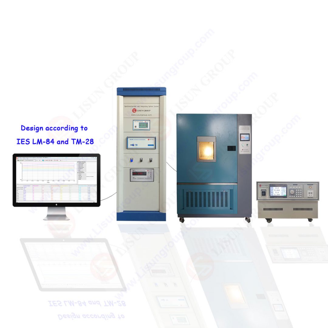
LISUN offers two primary configurations tailored to distinct industry standards. The LEDLM-80PL is designed for IES LM-80 and TM-21 compliance, supporting LED packages, arrays, and modules with test durations up to 6000 hours at three case temperatures (typically 55°C, 85°C, and a user-selected third temperature). The LEDLM-84PL targets IES LM-84 and TM-28 for LED lamps and luminaires, accommodating larger form factors and higher power outputs. Both systems share a common software platform but differ in hardware—the LEDLM-84PL uses larger integrating spheres (up to 2 meters in diameter) to handle beam angles up to 120 degrees without significant absorption errors.
2.2 Customizable Hardware Configurations
Each system supports up to 3 connected temperature chambers, enabling simultaneous testing at multiple stress levels. The chambers maintain stability within ±1°C of setpoints, critical for Arrhenius Model accuracy. Engineers can configure channel counts from 20 to 80 test positions per chamber, depending on sample size requirements. For calibration, the system includes reference LEDs with NIST-traceable photometric data, allowing automated cross-checking of measurement drift over time. Table 1 compares key specifications between the two variants.
Table 1: Comparison of LEDLM-80PL and LEDLM-84PL Specifications
| Parameter | LEDLM-80PL | LEDLM-84PL |
|---|---|---|
| Applicable Standard | IES LM-80, TM-21 | IES LM-84, TM-28 |
| Test Duration | Up to 6,000 hours | Up to 6,000 hours |
| Max Temperature Chambers | 3 | 3 |
| Integrating Sphere Diameter | 0.3 m – 1.0 m | 1.0 m – 2.0 m |
| Sample Type | Packages, arrays, modules | Lamps, luminaires |
| Lumen Maintenance Metrics | L70, L50 | L70, L50 |
| Temperature Stability | ±1.0°C | ±1.0°C |
| Photometric Accuracy | ±2% (luminous flux) | ±2% (luminous flux) |
3.1 Constant Current Mode Calibration
In constant current mode, the system maintains a fixed drive current (e.g., 350 mA, 700 mA, 1 A) across all test samples regardless of temperature-induced voltage shifts. Calibration involves verifying current stability using a precision shunt resistor (0.1% tolerance) and a 6.5-digit multimeter. The LISUN software logs current values every 10 seconds, triggering alarms if deviations exceed ±0.5%. Engineers must also calibrate the current source against a reference load at each test temperature, as output impedance varies with ambient conditions. Drift compensation algorithms built into the LEDLM-80PL automatically adjust for thermal expansion in measurement circuits.
3.2 Constant Temperature Mode Calibration
Constant temperature mode requires precise control of the LED junction temperature, typically measured via a thermocouple attached to the thermal pad. Calibration steps include:
- Verifying temperature chamber uniformity using a 9-point mapping method (per CIE 70 guidelines)
- Matching thermocouple readings with the system’s PID controller output
- Performing a 24-hour stability test at each setpoint (55°C, 85°C, 105°C) with a reference LED
- Adjusting thermal grease application height to maintain consistent thermal resistance (Rth junction-to-case)
The LEDLM-84PL’s software includes a thermal resistance calculator that corrects for ambient temperature gradients, ensuring junction temperature accuracy within ±2°C for all test positions.
4.1 Absolute Luminous Flux Calibration
The integrating sphere measures total luminous flux by comparing sample output against a calibrated standard lamp. For LEDLM-80PL systems with 0.5-meter spheres, calibration uses a 1000-lumen standard lamp traceable to NIST, placed at the sphere center. The sphere must be tested for self-absorption effects at each test interval, particularly for samples with spectral distributions different from the calibration standard. LISUN’s software includes an auxiliary lamp method where a secondary reference LED flashes between measurements, allowing real-time correction for sphere coating degradation—a process aligned with CIE 084 recommendations.
2.2 Spectral Mismatch and Colorimetric Calibration
LEDs exhibit narrow spectral bandwidths, often causing errors in photometric measurements when using standard photopic correction filters. The LISUN system employs a spectroradiometer (350–1050 nm range) for spectral power distribution (SPD) measurements. Calibration involves:
- Wavelength accuracy verification using a low-pressure mercury lamp (line peaks at 546.1 nm and 435.8 nm)
- Stray light correction using the Bunsen-Roscoe law
- Integration of SPD data using CIE 192:2010 weighting functions
For colorimetric metrics (CCT, CRI), calibration requires reference LEDs with known chromaticity coordinates certified to ±0.005 (u’, v’) uncertainty. This ensures accurate TM-21 projections that are sensitive to phosphor degradation spectra.
5.1 Sampling Frequency and Noise Reduction
Calibration of the data acquisition system is essential for reliable lumen maintenance curves. The LISUN platform samples every 30 minutes during the first 1000 hours, then transitions to hourly sampling for the remaining 5000 hours. Engineers must verify that the analog-to-digital converter (24-bit resolution) operates without drift by injecting a known voltage from a calibrator at 0-hour, 3000-hour, and 6000-hour milestones. The software applies a moving average filter (window size: 5 samples) to reduce photodetector shot noise, but calibration must confirm that this filter does not obscure rapid degradation events—particularly critical for early-life failures in LED modules.
5.2 TM-21 Extrapolation Algorithm Validation
TM-21 requires projecting L70/L50 values at 6 times the test duration (e.g., 36,000 hours from 6,000-hour data). Calibration involves:
- Inputting a synthetic dataset with known decay rates (0.5%, 1%, 2% per 1000 hours)
- Comparing software output with manual calculations using the exponential decay model: Φ(t) = β × exp(-αt)
- Verifying that the system correctly applies Arrhenius normalization when extrapolating from multiple temperatures
- Testing edge cases: datasets with fewer than 4,000 hours (TM-21 minimum) or noisy measurements
The LISUN LEDLM-84PL software includes a validation module that flags extrapolations exceeding ±20% of expected values, helping engineers identify calibration drift before it affects final reports.
6.1 Multi-Chamber Synchronization
When using 3 connected temperature chambers, calibration must ensure synchronized data logging and thermal profiles. LISUN’s master controller communicates via RS-485 with each chamber, polling temperature readings every 10 seconds. Engineers must verify that the time stamps across chambers align within ±1 second to avoid phase errors in Arrhenius calculations. A common issue is thermal lag: when one chamber ramps from 55°C to 85°C, the system must pause data collection until all chambers stabilize. Calibration includes programming ramp rates (2°C/minute maximum) and soak times (30 minutes) into the software’s state machine.
6.2 Environmental Stressors and Correction Factors
External factors like ambient humidity and line voltage fluctuations affect calibration stability. The LISUN system includes:
- Humidity sensors (range: 20%–80% RH) that trigger warnings above 60% RH
- Power line conditioners (voltage regulation ±0.1%)
- Internal reference LEDs that measure baseline drift every 24 hours
During annual calibration, engineers must perform a 72-hour stability run with all chambers active, monitoring reference flux drift. Any deviation beyond ±0.5% requires adjusting the compensation table in the software, a procedure documented in LISUN’s service manual for both LM-80 and LM-84 systems.
7.1 Routine Verification Using Test Artifacts
Between full calibrations (recommended every 12 months), weekly verification checks maintain system confidence. LISUN provides:
- Two reference LEDs: one stable (lumen maintenance >95% at 1000 hours) and one degraded (lumen maintenance ~80% at 1000 hours)
- Automated verification sequence: place reference in each chamber, run a 1-hour test, compare results against stored baseline values
- Action limits: ±2% for luminous flux, ±50 K for CCT, and ±1.0 for CRI
If any parameter exceeds these limits, the software generates a calibration alert and recommends repeating the full calibration procedure from Section 3.
7.2 Report Generation and Standards Compliance
The final calibration report must include:
- Measurement uncertainty budgets per ISO Guide 17025
- Raw data plots with TM-21 curve fits
- L70/L50 values with 95% confidence intervals
- Temperature stability logs for each chamber
- Cross-references to IES LM-80, IES LM-84, TM-21, and TM-28 requirements
LISUN’s report generator automates this process, but engineers must verify that all numerical data (e.g., activation energy, correlation coefficients) are correctly transferred from the calibration database. A final sign-off requires comparing system-reported values with manual calculations for three randomly selected test positions.
Calibrating an LED lumen maintenance test system demands meticulous attention to photometric accuracy, temperature control, and compliance with standards such as IES LM-80, IES LM-84, TM-21, and TM-28. The LISUN LED Lumen Maintenance Test System, through its LEDLM-80PL and LEDLM-84PL variants, provides a robust platform for achieving these goals. By mastering dual testing modes, integrating sphere calibration, and Arrhenius Model validation, engineers can ensure that 6000-hour test data accurately predicts L70/L50 lifetimes for any LED product—whether packages, modules, lamps, or luminaires. The system’s support for up to 3 temperature chambers and customizable configurations addresses the diverse needs of manufacturers and test labs. From routine weekly verifications to annual full calibrations, the procedures outlined in this guide align with global best practices and deliver repeatable, auditable results. Adopting these calibration methods reduces measurement uncertainty below ±2% and strengthens confidence in lifetime declarations, ultimately supporting safer, more reliable LED products for the lighting industry.
Q1: How often should I perform a full calibration of the LISUN LED Lumen Maintenance Test System?
A: Full calibration should be performed annually, or after any major system modification (e.g., replacing an integrating sphere coating, upgrading temperature chambers, or installing new software versions). The calibration includes verifying photometric accuracy using NIST-traceable reference standards, temperature chamber uniformity per CIE 70 guidelines, and TM-21 extrapolation algorithms. For high-volume production labs, LISUN recommends quarterly verification using the built-in test artifacts (reference LEDs with known decay rates). Weekly checks using the automated reference sequence can catch early drifts before they affect production data. Always document calibration dates and results in accordance with ISO 17025 requirements for traceability and audits.
Q2: What are the most common calibration errors in LED lumen maintenance systems, and how does LISUN’s design mitigate them?
A: Common errors include spectral mismatch due to changing phosphor emission, temperature drift in photodetectors, and sphere coating degradation over time. LISUN mitigates these through: (1) spectroradiometer-based SPD measurement that eliminates filter-based photometer errors; (2) dual Peltier-cooled detectors with ±0.1°C temperature stabilization; and (3) an auxiliary lamp method that automatically corrects for sphere absorption changes. Additionally, the software’s Arrhenius Model includes a self-diagnostic routine that flags data points with high leverage (>0.3) in regression analysis, alerting engineers to potential calibration issues. Performing monthly white-balance checks using a reference LED helps maintain long-term accuracy.
Q3: Can the LISUN system be calibrated for different LED types (e.g., high-power, mid-power, COB, and UV LEDs)?
A: Yes, but calibration settings must be tailored to the LED type. For high-power LEDs (>5W), ensure the integrating sphere driver current can handle up to 3 A continuously without overheating—the LEDLM-84PL’s active cooling loop supports this. For UV LEDs (peak emission below 400 nm), the spectroradiometer requires a separate calibration using a deuterium lamp source (traceable to NIST) rather than the standard tungsten lamp. COB LEDs with wide emission angles (>120°) may need a larger sphere diameter to avoid wall absorption errors—use the 2.0-meter sphere option. LISUN provides application-specific calibration kits for each category, including reference LEDs with known luminous flux and spectral data for the target wavelength range.