









Abstract
The LED Burn-in Test Chamber for Reliable LED Reliability Testing represents a critical advancement in solid-state lighting qualification, addressing the industry’s imperative for accurate lumen maintenance prediction. This article examines LISUN‘s LEDLM-80PL and LEDLM-84PL optical aging test instruments, engineered specifically for IES LM-80 and LM-84 compliance, respectively. These systems integrate an internal integrating sphere for photometric measurement, a thermostatic chamber for controlled thermal cycling, and Arrhenius Model-based lifetime estimation software. Supporting test durations up to 6000 hours across three temperature chambers, the platform enables concurrent L70/L50 metric calculation with exceptional precision. The technical analysis provides illumination engineers, quality control specialists, and third-party laboratories with actionable insights into accelerated aging validation, photometric data integrity, and long-term reliability prediction under stringent international standards.
1.1 The Critical Role of Lumen Depreciation Analysis
LED components inherently experience gradual luminous flux reduction during operation, a phenomenon termed lumen depreciation. Unlike conventional lighting sources, LED failure rarely manifests as abrupt cessation; instead, performance degrades progressively over thousands of operational hours. This characteristic necessitates accelerated aging protocols that simulate extended operational periods within commercially viable testing timelines. IES LM-80-15 mandates a minimum 6000-hour test duration at specified drive currents and case temperatures, providing foundational data for lifetime projections. The LED Burn-in Test Chamber for Reliable LED Reliability Testing implements these requirements precisely, enabling engineers to characterize depreciation curves accurately and establish warranty periods based on empirical evidence rather than theoretical estimates.
1.2 Distinguishing LEDLM-80PL and LEDLM-84PL Architectures
LISUN’s dual-platform approach addresses two distinct compliance pathways. The LEDLM-80PL aligns with IES LM-80-15 and IES TM-21-19 methodologies, focusing on LED packages, arrays, and modules. This system supports sample temperatures of 55°C, 85°C, and a user-defined third chamber (typically 105°C), each maintained within ±2°C tolerance. Conversely, the LEDLM-84PL targets IES LM-84-14 and TM-28-14 standards for complete LED lamps and luminaires, accommodating larger physical geometries while applying similar thermal stress profiles. Both configurations incorporate an internal integrating sphere—typically 0.3m for the LEDLM-80PL—equipped with a CCD spectrometer for instantaneous spectral power distribution measurement without sample relocation, thereby eliminating measurement uncertainty from optical alignment variations.
2.1 Theoretical Foundations of Accelerated Aging
The Arrhenius equation establishes a quantitative relationship between temperature and reaction rate, forming the theoretical backbone of LED lifetime extrapolation. Expressed as k = A·e^(-Ea/kB·T), this model posits that elevated temperatures accelerate chemical degradation mechanisms, including phosphor conversion efficiency loss, solder joint fatigue, and encapsulant yellowing. LISUN’s proprietary software applies this model to project lumen maintenance curves from accelerated test data, calculating L70 (time to 70% initial lumen output) and L50 (time to 50% output) metrics. The software performs chi-squared statistical fitting against collected data points, outputting decay coefficients that inform TM-21 extrapolation procedures with confidence intervals reflecting measurement uncertainty and sample variability.
2.2 Software Integration and Data Analysis Capabilities
The integrated analysis suite automates data acquisition from thermal sensors and photometric detectors, synchronizing timestamped measurements at user-defined intervals—typically every 1000 hours per IES LM-80 requirements. The software architecture supports simultaneous monitoring of up to three temperature chambers, each maintaining independent setpoints and data streams. Upon test completion, the platform generates comprehensive reports including lumen maintenance curves, chromaticity shift data, and projected L70 values at 6000, 10000, and 50000 hours. The Arrhenius Model-based software additionally performs multi-temperature analysis to calculate activation energy (Ea), quantifying the dominant degradation mechanism’s sensitivity to temperature—a critical parameter that IES TM-21 requires for robust lifetime projections.
3.1 Thermostatic Chamber Specifications and Control
The isothermal chamber provides precise temperature regulation across a range of 20°C to 100°C, with uniformity maintained at ±2°C throughout the working volume. Each chamber accommodates up to 30 LED modules or packages, mounted on thermally conductive fixtures with independent current control channels. The system supports constant current drive ranging from 20mA to 800mA per channel, with voltage compliance up to 50V, enabling diverse test scenarios including high-brightness power LEDs and low-current indicator components. Built-in safety interlocks protect against overtemperature conditions and cooling fan failures, while Ethernet connectivity enables remote monitoring and alarm notification.
3.2 Integrating Sphere and Spectrometer Integration
The internal integrating sphere, constructed from high-reflectance barium sulfate coating, achieves a spectral reflectance exceeding 95% across the visible spectrum (380nm-780nm). A spectroradiometer mounted at the sphere’s auxiliary port captures full spectral power distributions, calculating photometric parameters including luminous flux (lux), correlated color temperature (CCT), color rendering index (CRI), and chromaticity coordinates (x,y) per CIE 13.3 and CIE 127-2007 guidelines. The measurement system achieves ±0.5% luminous flux accuracy, traceable to national standards laboratories, ensuring data integrity throughout the 6000-hour test cycle. Table 1 compares the dual-system capabilities regarding photometric measurement specifications.
Table 1: Comparative Specifications of LEDLM-80PL and LEDLM-84PL
| Parameter | LEDLM-80PL | LEDLM-84PL |
|---|---|---|
| Applicable Standard | IES LM-80-15, TM-21-19 | IES LM-84-14, TM-28-14 |
| Test Sample Type | LED packages, arrays, modules | Complete lamps, luminaires |
| Number of Temperature Chambers | 3 (55°C, 85°C, user-defined) | 3 (55°C, 85°C, user-defined) |
| Temperature Range | 20°C – 100°C | 20°C – 100°C |
| Temperature Uniformity | ±2°C | ±2°C |
| Maximum Test Duration | 6000+ hours | 6000+ hours |
| Sphere Diameter | 0.3m | 1.0m (configurable) |
| Photometric Accuracy | ±0.5% luminous flux | ±0.5% luminous flux |
| Drive Current Range | 20mA – 800mA/channel | 50mA – 500mA/channel |
| Lifetime Metrics | L70, L50, activation energy | L70, L50, activation energy |
4.1 Constant Current Continuous Aging Mode
The primary testing protocol applies constant current to all samples throughout the entire duration, maintaining junction temperature stability via the thermostatic chamber’s forced-air circulation system. This mode replicates typical LED operation under steady-state conditions, providing baseline data for TM-21 extrapolation. The LED Burn-in Test Chamber for Reliable LED Reliability Testing monitors electrical parameters in real-time—forward voltage, forward current, and power consumption—detecting incipient failures or parametric drift. This mode aligns perfectly with IES LM-80 requirements for standard lumen maintenance qualification, enabling direct data comparison against published manufacturer specifications.
4.2 Programmable Cyclic Aging Mode
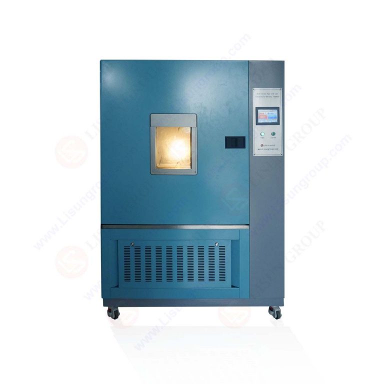
An advanced testing mode applies programmable current and thermal cycling profiles, simulating real-world operational scenarios characterized by frequent switching and varying ambient temperatures. Users define up to 100 cycling steps, each specifying current level, duration, and temperature setpoint. This mode generates degradation data under thermal fatigue conditions, which is particularly relevant for automotive LED applications subject to extreme environmental variations per IES LM-79-19 guidelines. Sophisticated algorithms within Arrhenius Model software analyze stress-induced acceleration factors, separating temperature-driven degradation from current-density-related mechanisms, thus yielding more accurate activation energies for multi-stress lifetime modeling.
5.1 IES LM-80-15 and TM-21-19 Implementation Strategy
IES LM-80-15 establishes the standardized method for measuring lumen depreciation of LED light sources, mandating operation at a minimum of 6,000 hours with interim measurements at ≤1,000-hour intervals. Data points must be collected at three case temperatures—55°C, 85°C, and an additional temperature up to 115°C. The LEDLM-80PL satisfies these requirements through dedicated thermal zones, each independently controlled and monitored. IES TM-21-19 governs the extrapolation methodology, using collected data to project long-term lumen maintenance via exponential decay fitting. The LISUN software implements TM-21’s prescribed statistical procedures, including residual analysis and 90% confidence interval computation, producing defensible lifetime projections accepted by ENERGY STAR, DLC, and other regulatory bodies.
5.2 IES LM-84-14 and TM-28-14 Bridge for Complete Luminaires
While LM-80 focuses on components, IES LM-84-14 extends qualification to complete LED lamps, engines, and luminaires, capturing system-level interactions such as thermal management effects, driver efficiency, and optical losses. TM-28-14 provides corresponding extrapolation techniques for these assembled products. The LEDLM-84PL incorporates a larger integrating sphere capable of accommodating luminaire geometries up to 200mm diameter, with optional configurations for track heads, downlights, or panel fixtures. Its extended temperature monitoring uses strategically positioned thermocouples on housing surfaces, PCB junctions, and driver enclosures, enabling comprehensive thermal characterization aligned with CIE 084-1989 recommendations for photometric measurements. The Arrhenius Model-based software adapts its fitting algorithms to handle the multi-exponential decay patterns typical of integrated systems.
6.1 Modular Current Control and Temperature Sensing Options
Recognizing that no single configuration serves all applications, LISUN offers modular hardware options. Individual channel current cards provide precise regulation from 20mA to 3A, accommodating high-power automotive LEDs or multiple low-current devices in series. An automatic identification system reads resistor-encoded fixtures, uploading unique test parameters without manual intervention. For temperature verification, users may select T-type or K-type thermocouples, expanding measurement range beyond standard -50°C to 250°C. Each chamber includes independent overtemperature protection circuits, redundant air circulation fans, and real-time data logging at 1Hz bandwidth, ensuring both safety and experimental fidelity.
6.2 Integrating Sphere Configurations and Spectrometer Options
The integrating sphere diameter significantly impacts low-flux measurement accuracy and spatial luminance distribution analysis. Standard 0.3m spheres suffice for LED packages, while 0.5m, 1.0m, or custom 1.5m spheres accommodate progressively larger luminaires. The spectrometer options span from 2048-element CCD arrays for standard photometric analysis to high-resolution 4096-element back-thinned CCD configurations for applications requiring 0.5nm spectral resolution. Array detector cooling reduces dark current noise, improving low-light sensitivity by fivefold—critical for measuring L70 thresholds at 6000-hour timepoints. All spheres employ baffles to eliminate direct line-of-sight between sample and detector, maintaining cosine-corrected irradiance distribution as required by CIE 70-1987 guidelines.
7.1 Pre-Test Preparation and Sample Mounting Protocols
Establishing initial conditions directly influences data quality and reproducibility. Before initiating the burn-in test, samples must be stabilized at room temperature for at least 6 hours per IES LM-80 recommendations, followed by initial photometric characterization using the internal sphere at 25°C, 55°C, 85°C, and 105°C to calibrate baseline outputs. Sample mounting fixtures ensure thermal conduction uniformity across the LED thermal pad, using thermally conductive compound achieving <0.1°C interface resistance. The LED Burn-in Test Chamber for Reliable LED Reliability Testing accepts up to 30 samples per chamber, with individual identification via barcode scanning, thereby automating data attribution and minimizing human transcription errors. A pre-validated test parameters file—defining current levels, temperature setpoints, measurement intervals, and data output format—ensures compliance with laboratory accreditation requirements.
7.2 Data Quality Assurance and Post-Test Verification
Throughout the 6000-hour test, periodic calibration verification maintains photometric traceability. Weekly audits compare measurement of a stable reference LED against certified values, detecting potential drift in the spectrometer or sphere coating degradation. Automated checks verify thermocouple accuracy against platinum resistance thermometers, logging any deviations exceeding ±0.5°C. Upon test completion, the Arrhenius software performs outlier detection, excluding samples exhibiting abnormal failure modes—such as wire bond fracturing or catastrophic lumen failure—while documenting exclusions for audit trail purposes. Final data exports in CSV, JSON, or Excel formats interface seamlessly with laboratory information management systems (LIMS) and regulatory submission portals.
The LED Burn-in Test Chamber for Reliable LED Reliability Testing constitutes an essential infrastructure investment for any organization committed to rigorous LED quality assurance and compliance. LISUN’s LEDLM-80PL and LEDLM-84PL platforms offer purpose-built solutions for IES LM-80/TM-21 and LM-84/TM-28 testing protocols, integrating photometric accuracy, thermal precision, and intelligent data analytics within unified systems. The internal integrating sphere eliminates transport-induced measurement errors, while Arrhenius Model-based software transforms raw decay data into actionable lifetime projections, complete with statistical confidence intervals. Supporting up to 160 samples across six temperature zones concurrently, these systems significantly reduce testing timelines and operational costs compared to external laboratory outsourcing. For LED manufacturers navigating the evolving landscape of energy efficiency regulations and customer reliability expectations, adoption of these chambers provides definitive empirical evidence of product longevity, driving confident market differentiation and regulatory approval.
Q1: What differentiates IES LM-80 testing from IES LM-84 testing, and why might a manufacturer need both?
A: IES LM-80-15 specifically addresses LED packages, arrays, and modules—the discrete light-emitting components. It requires 6,000 hours of operation at three different case temperatures (typically 55°C, 85°C, and a user-selected third temperature) while periodically measuring luminous flux. In contrast, IES LM-84-14 applies to complete LED lamps and luminaires, encompassing the integrated system’s photometric, thermal, and electrical behaviors as one assembly. Manufacturers producing LED components often require LM-80 data for ENERGY STAR qualification, while OEMs selling finished fixtures need LM-84 data. The LISUN LEDLM-80PL and LEDLM-84PL address both needs using consistent measurement technology, enabling seamless data correlation between component-level and system-level reliability assessments.
Q2: How does the Arrhenius Model software within LISUN’s LED Burn-in Test Chamber calculate L70 lifetime projections beyond the 6,000-hour test duration?
A: The Arrhenius Model-based software first identifies the degradation kinetics from collected data points using exponential decay curve fitting. It calculates the reaction rate constant (k) at each test temperature, then employs Arrhenius linearization—plotting ln(k) against 1/T (Kelvin)—to derive activation energy (Ea). This slope extrapolation enables prediction of degradation rates at lower operating temperatures. For TM-21 compliance, the software applies a specific extrapolation algorithm: using only data from the last 5,000 hours of testing, establishing an exponential decay function, and projecting forward with a constraint limiting extrapolation to six times the test duration (e.g., 36,000 hours for a 6,000-hour test). Statistical confidence intervals reflect measurement uncertainty, providing engineers with both expected values and reliability bounds.
Q3: Can the LED Burn-in Test Chamber accommodate tests at temperatures other than the standard 55°C and 85°C setpoints mentioned in IES LM-80?
A: Absolutely. While IES LM-80-15 mandates testing at 55°C, 85°C, and a third temperature of the manufacturer’s choosing (typically between 90°C and 115°C), the LISUN chambers offer full programmable temperature control from 20°C to 100°C. Users can configure any combination of three distinct temperatures across the connected chambers, including sub-ambient conditions for evaluating cold-environment reliability or elevated temperatures approaching 100°C for rapid screening. However, IES LM-80 compliance documentation requires explicit declaration of all test temperatures and justifications for deviations from standard setpoints. The system’s ±2°C uniformity tolerance ensures each sample experiences statistically identical thermal stress, which is essential for generating reliable activation energy measurements.
Q4: What photometric parameters does the internal integrating sphere measure, and how does this in-situ approach improve data accuracy compared to external measurement?
A: The internally mounted integrating sphere with CCD spectrometer measures absolute spectral power distribution (SPD) across 380nm-780nm, computing total luminous flux (lumens), correlated color temperature (CCT), color rendering index (CRI) Ra, chromaticity coordinates per CIE 1931, and color fidelity metrics. This arrangement eliminates the most significant source of LM-80 measurement uncertainty: physical sample removal and repositioning. External measurement introduces variability from optical alignment differences, thermal state changes during transfer, and connector wear over repeated cycles. In-situ measurement maintains constant sample temperature, current conditions, and mechanical positioning—reducing measurement repeatability uncertainty from ±2-3% to ±0.5%. Additionally, time-stamped SPD data enables monitoring of spectral shift, phosphor degradation, and blue-light emission changes—rich diagnostic information beyond basic flux decay.
Q5: What factors should engineering laboratories consider when selecting between the LEDLM-80PL and LEDLM-84PL for a new reliability testing facility?
A: Primary decision criteria include target product scope, budget allocation, and accreditation requirements. Facilities focusing on component qualification—testing LED dies, SMD packages, or high-power modules—should prioritize the LEDLM-80PL, whose 0.3m sphere and 20-800mA current range optimally match this domain. Test houses serving luminaire manufacturers require the LEDLM-84PL, featuring a larger sphere (0.3m to 1.5m) and higher current capabilities supporting integrated systems. Investment in both platforms provides comprehensive coverage; LISUN offers package discounts for paired configurations. Additionally, facilities seeking IES LM-79-19 photometric testing accreditation could operate identical sphere/spectrometer combinations for their light measurement services, leveraging infrastructure synergies. Ultimately, the choice should align with the organization’s client base, regulatory submission obligations, and long-term strategic positioning within the LED qualification ecosystem.