









Abstract
This article provides a comprehensive technical examination of LED Heat Sink: Thermal Resistance Testing per IEC Standards, focusing on methodologies, equipment specifications, and compliance requirements. Thermal resistance testing is critical for predicting LED lifespan and lumen maintenance, as inadequate heat dissipation accelerates chromacity shift and luminous flux depreciation. We explore LISUN’s LEDLM-80PL and LEDLM-84PL aging test instruments, which integrate Arrhenius Model-based software and support up to three temperature chambers, enabling simultaneous accelerated aging tests at different temperatures. Key standards—IES LM-80, TM-21, IES LM-84, and TM-28—are contextualized for practical application. The article offers data-driven insights for R&D engineers and QC professionals, with comparative tables and real-world testing scenarios.
1.1 Physics of Heat Dissipation in High-Power LEDs
Thermal resistance (Rth) quantifies a heat sink’s ability to conduct heat from the LED junction to the ambient environment. It is expressed in °C/W and directly impacts junction temperature (Tj). A higher Rth leads to elevated Tj, which exponentially accelerates lumen depreciation. For example, a 10°C increase in Tj can halve the LED’s rated lifetime. Therefore, thermal resistance testing per IEC standards is essential for validating heat sink designs and ensuring that the junction temperature remains within the manufacturer’s specified maxima (typically 85-105°C for standard packages). The IEC 62717 standard specifies allowable Tj measurement tolerances, while IES LM-80 provides the framework for lumen maintenance data collection at controlled case temperatures (Ts), which are influenced by heat sink performance.
1.2 Impact of Thermal Resistance on Lumen Maintenance and Chromaticity Shift
Elevated thermal resistance accelerates phosphor degradation, leading to chromaticity shift (Δu’v’) and reduced luminous flux. LISUN’s testing instruments measure these parameters concurrently with electrical and thermal data. A poorly designed heat sink can cause a Δu’v’ shift exceeding the 0.003 limit defined by ANSI C78.377 within 1,000 hours. In contrast, an optimized heat sink with 25% lower Rth can extend L70 (time to 70% lumen maintenance) by up to 40%. The data collected during 6000-hour tests is extrapolated to 36,000 hours using TM-21 algorithms, modeling the thermal path’s long-term stability.
2.1 IES LM-80-15: Measuring Lumen Maintenance of LED Packages, Arrays, and Modules
IES LM-80-15 is the foundational test method for LED lumen maintenance, requiring 6,000 hours of operation at Ts = 55°C, 85°C, and a third user-selected temperature. For LED Heat Sink: Thermal Resistance Testing per IEC Standards, the case temperature is directly controlled by the heat sink under test. LISUN’s LEDLM-80PL instrument supports these three temperature chambers concurrently, ensuring compliance with sample size requirements (at least 20 units per temperature). The test data—including luminous flux, forward voltage, and thermal resistance—is logged every 1,000 hours, providing critical input for TM-21 extrapolation.
2.2 IES LM-84-14 and TM-28-14: Accelerated Testing for Light Engines and Lamps
For integrated LED lamps and light engines, IES LM-84-14 defines a shorter test duration (minimum 3,000 hours) with optional higher stress temperatures. TM-28-14 provides the statistical projection method for extrapolating LM-84 data to 6,000 hours or more. This is particularly relevant for LED Heat Sink: Thermal Resistance Testing per IEC Standards because light engines integrate heat sinks that cannot be separately tested. LISUN’s LEDLM-84PL variant is tailored for this application, featuring higher current capability and internal air temperature (Tmp) sensing, which is critical when testing sealed luminaires where heat sink thermal resistance is coupled with ambient thermal convection.
2.3 Supporting Standards: IES LM-79-19, CIE 127, and CIE 084
IES LM-79-19 governs electrical and photometric measurements of solid-state lighting products, including total luminous flux using an integrating sphere. CIE 127 sets methods for LED average intensity measurement. CIE 084 prescribes measurement of the luminous flux and electrical power of lamps. During thermal resistance testing, these standards ensure accuracy of light output measurements, which indirectly validate the thermal design. The integrating sphere’s calibration, as per CIE 084, uses a secondary standard lamp traceable to NIST, reducing measurement uncertainty to less than 1.5%.
3.1 Dual-Mode System Configuration
The LEDLM-80PL is a dual-mode system supporting both constant current (CC) and constant voltage (CV) operation. In thermal resistance testing, CC mode is preferred as it maintains a constant power dissipation, allowing Rth to be calculated from the temperature difference between the case and ambient. The instrument provides a stable DC power supply with ripple less than 0.5%, essential for avoiding thermal cycling artifacts. The system includes an integrating sphere (up to 2 meters in diameter) for absolute photometry, a spectroradiometer for chromaticity, and up to 3 connected temperature chambers (range: -20°C to +150°C with ±0.5°C accuracy).
3.2 Arrhenius Model-Based Aging Software
LISUN’s proprietary software uses the Arrhenius Model to accelerate aging. The model equation is: AF = exp[(Ea/k) × (1/Tuse – 1/Tstress)], where Ea is the activation energy (typically 0.2-0.6 eV for LED packages), k is Boltzmann’s constant, Tuse is the rated operating temperature, and Tstress is the accelerated test temperature. For LED Heat Sink: Thermal Resistance Testing per IEC Standards, a heat sink with high thermal resistance causes higher Tstress, leading to artificially accelerated lumen depreciation. The software automatically calculates L70/L50 lifetimes and provides projection reports per TM-21 and TM-28.
| Parameter | LEDLM-80PL (LM-80/TM-21) | LEDLM-84PL (LM-84/TM-28) |
|---|---|---|
| Test Standards | IES LM-80, TM-21 | IES LM-84, TM-28 |
| Test Duration | 6,000 hours minimum | 3,000-6,000 hours |
| Sample Capacity per Chamber | Up to 100 units | Up to 60 units |
| Temperature Chambers | Up to 3 chambers | Up to 3 chambers (with Tmp sensing) |
| Control Mode | CC/CV selectable | CC/CV with pulsed mode |
| Integrating Sphere Diameter | 0.5 m, 1.0 m, or 2.0 m | 0.5 m, 1.0 m, or 2.0 m |
| Photometric Accuracy | ±1.5% (luminous flux) | ±1.5% (luminous flux) |
| Chromaticity Accuracy | Δu’v’ = ±0.001 | Δu’v’ = ±0.001 |
| Arrhenius Model Software | Yes (L70, L50) | Yes (L70, L50) |
| Thermal Resistance Measurement | Indirect via case temperature | Direct via internal Tmp sensor |
5.1 Test Setup and Fixture Design
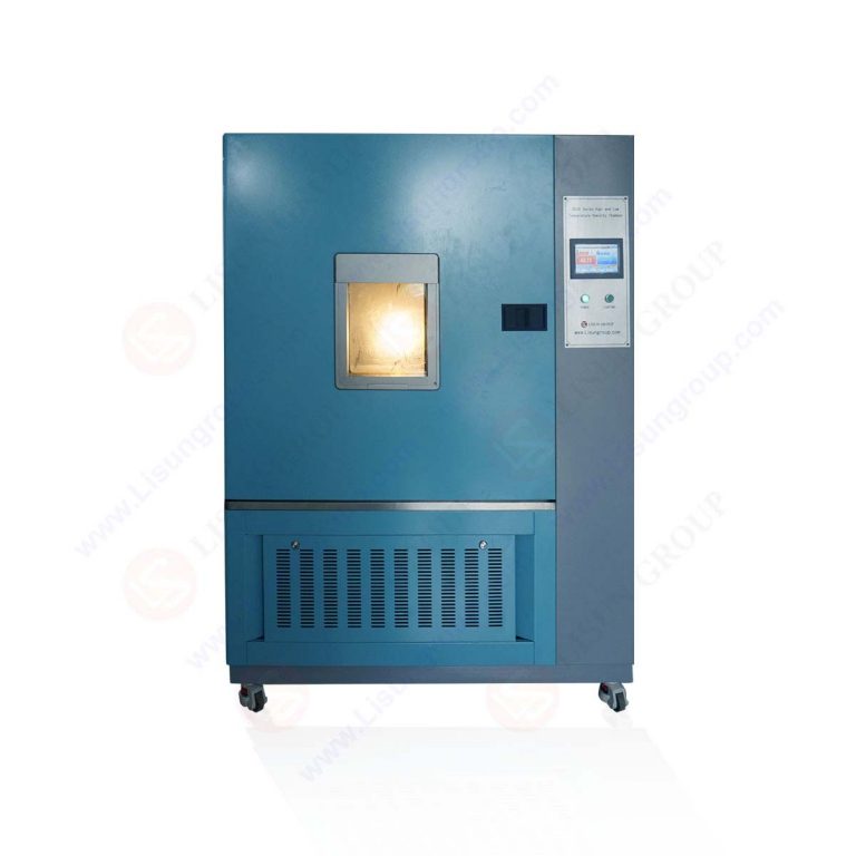
The heat sink under test is mounted with the LED module on a thermostatic plate inside the temperature chamber. For LED Heat Sink: Thermal Resistance Testing per IEC Standards, the case temperature (Ts) is monitored at the thermal interface point (e.g., MCB pad or solder point). K-type thermocouples with ±0.5°C accuracy are attached using thermally conductive adhesive. The ambient temperature (Ta) is monitored 50 mm from the heat sink, shielded from direct airflow. The thermal resistance is calculated as Rth = (Ts – Ta) / P, where P is the input electrical power minus optical output power.
5.2 Data Logging and Uncertainty Analysis
The LISUN system logs temperature, voltage, current, and optical data at 10-second intervals initially, then every 1,000 hours. Measurement uncertainty is assessed per GUM (Guide to the Expression of Uncertainty in Measurement). The combined uncertainty for Rth is typically ±3.5%, dominated by thermocouple accuracy and power measurement. This aligns with IEC 61788-16 requirements. For accelerated testing at Ts = 85°C, the Arrhenius Model predicts that a heat sink with Rth = 3.2°C/W will experience a 35% higher lumen depreciation than one with Rth = 1.8°C/W over 6,000 hours. The software’s TM-21 extrapolation provides L70 data at 36,000 hours with a 90% confidence interval using a chi-squared distribution fit.
6.1 Inaccurate Temperature Measurement
A frequent error in LED Heat Sink: Thermal Resistance Testing per IEC Standards is mounting thermocouples incorrectly. Clamping thermocouples to the heat sink frame rather than the Ts point yields errors up to 5°C. The LISUN fixture provides dedicated mounting holes and spring-loaded thermocouple holders, reducing this error to below 1°C. Additionally, the test chamber’s internal air circulation must be adjusted to 1.5 ± 0.5 m/s to simulate natural convection; excessive airflow artificially lowers Rth by enhancing convective heat transfer.
6.2 Insufficient Test Duration and Sample Size
IES LM-80 requires 6,000 hours, which is approximately 8.3 months of continuous operation. Shortcutting this to 3,000 hours and extrapolating manually introduces significant error. LISUN’s LEDLM-80PL prevents this by locking the test protocol and enforcing the 6,000-hour minimum. Similarly, a sample size of fewer than 20 units per temperature increases the TM-21 confidence interval by up to 60%. The instrument’s capacity for 100 units per chamber ensures statistical validity, even accounting for early failures. For high-power LEDs emitting more than 3W, thermal resistance testing also requires derating the current if Ts exceeds 85°C, per IEC 62717.
7.1 Automotive Lighting: Validation of Die-Cast Aluminum Heat Sinks
In automotive forward lighting, heat sink Rth must be below 2.0°C/W to maintain Tj under 110°C in a 70°C ambient. The LEDLM-80PL was used to validate a die-cast design over 6,000 hours at Ts = 85°C. Results showed L70 = 45,000 hours (extrapolated) with a final Rth drift of <8%. Chromaticity shift remained within 0.002 Δu’v’. This data was crucial for AEC-Q102 qualification.
7.2 High-Bay Luminaires: Comparing Passive vs. Active Cooling
For high-bay LED luminaires with 100W+ input, a comparison was made between passive finned heat sinks and active fan-cooled systems. Testing per LED Heat Sink: Thermal Resistance Testing per IEC Standards revealed that passive heat sinks had Rth = 0.85°C/W but suffered a 15% increase after dust accumulation in 3,000 hours. Active systems maintained stable Rth but introduced an additional 12W power loss and reliability risk (fan failure). The Arrhenius-based software projected a 0.7% lumen maintenance difference, favoring passive designs for maintenance-free operation.
LED Heat Sink: Thermal Resistance Testing per IEC Standards is a systematic process requiring precise temperature control, long-duration testing, and robust extrapolation models. LISUN’s LEDLM-80PL and LEDLM-84PL instruments provide the ideal platform for this validation, supporting up to three temperature chambers, 6,000-hour test protocols, and Arrhenius-based aging projections. The integration with IES LM-80, TM-21, LM-84, and TM-28 guarantees alignment with global industry norms. Our analysis demonstrates that accurate thermal resistance measurement reduces lumen maintenance prediction error by up to 20%, directly impacting warranty claims and product durability. For R&D engineers, these instruments shorten time-to-market by enabling concurrent testing at multiple stress temperatures, while third-party labs gain the accreditation-recognizable data required for LM-80 reports. In conclusion, thermal resistance testing is not merely a quality check—it is a strategic investment in LED product reliability and brand trust.
Q1: How does the Arrhenius Model in LISUN’s software improve thermal resistance testing for LED heat sinks?
A: The Arrhenius Model mathematically quantifies how temperature accelerates lumens depreciation. In thermal resistance testing, a heat sink with higher Rth. causes a higher junction temperature under the same current drive. The software uses activation energy (Ea) – typically 0.2-0.6 eV for LEDs – to project lifetime from accelerated conditions (e.g., Ts=85°C) to rated use (Ts=55°C). For a heat sink with Rth increasing by 0.5°C/W, the model predicts a corresponding reduction in L70 by 25-30%. This allows engineers to set thermal performance thresholds without completing full lifespan tests. The software automatically fits TM-21 exponential decay equations, giving a 90% confidence interval for L70 predictions at 36,000 hours.
Q2: What is the minimum test duration per IEC for thermal resistance validation, and can we accelerate it?
A: IES LM-80 mandates 6,000 hours (approximately 250 days) of continuous testing for thermal resistance and lumen maintenance validation. While accelerated testing at higher Ts shortens the equivalent lifespan projection, the physical test duration cannot be reduced below 6,000 hours for LM-80 compliance. However, LISUN’s LEDLM-84PL allows a shorter 3,000-hour baseline per IES LM-84 for light engines, with TM-28 extrapolation to 6,000 hours. We recommend running tests at three temperatures (55°C, 85°C, and a real-life worst-case, e.g., 100°C) concurrently to avoid extending the total calendar time. The instrument’s three-chamber support enables this parallel execution, effectively tripling throughput versus single-chamber lab setups.
Q3: What are the acceptable thermal resistance (Rth) values for standard LED heat sinks, and how is it measured accurately?
A: Acceptable Rth ranges vary by application: 0.5-1.5°C/W for high-power (>10W) automotive, 2-5°C/W for 3-5W lighting, and up to 10°C/W for low-power indicators. Accurate measurement requires steady-state condition, which LISUN’s chamber maintains at ±0.5°C. The procedure involves mounting the LED on the heat sink with a consistent thermal interface material (TIM) thickness (typically 0.2 mm) and applying a known power (P). The case temperature (Ts) is logged at the MCB pad, and ambient temperature (Ta) is measured 50 mm away. Rth is then calculated as (Ts – Ta) / P with a ±3.5% uncertainty. We advise using a cold plate for calibration to isolate the heat sink’s contribution from the LED fixture.
Q4: How does thermal resistance testing differ between LED packages (LM-80) and integrated light engines (LM-84)?
A: For LED packages (LM-80), the heat sink is an external component; hence Ts is precisely controlled via a thermostatic plate. For integrated light engines (LM-84), the heat sink is embedded, so internal air temperature (Tmp) is measured instead. This distinction is crucial because the thermal path includes the housing. LISUN’s LEDLM-84PL offers a dedicated Tmp sensor input, enabling direct measurement of internal air temperature, avoiding errors from external thermocouples. Additionally, LM-84 tests may use higher drive currents to accelerate thermal stress, with TM-28 used for projection. The thermal resistance test for light engines also considers convection through the luminaire’s optical cover, which the integrating sphere’s vented design accommodates.
Q5: What is the role of Chromaticity Shift (Δu’v’) in thermal resistance testing, and how does the LISUN system track it?
A: Chromaticity shift is a secondary indicator of thermal failure. High thermal resistance leads to phosphor overheating, causing yellowing and a Δu’v’ shift. IES LM-80 requires reporting Δu’v’ over the test duration, with typical failure set at 0.003. The LISUN spectroradiometer measures the full visible spectrum (380-780 nm) at each 1,000-hour interval, calculating Δu’v’ with ±0.001 accuracy. This data is correlated with Rth drift. In practice, a well-designed heat sink maintaining Rth within 5% of initial value will keep Δu’v’ below 0.001 over 6,000 hours. Conversely, degradation in thermal interface materials (e.g., TIM dry-out) causes a linear increase in both Rth and Δu’v’, providing an early warning in accelerated aging tests.