









Abstract
This technical article examines LED thermal resistance testing as a critical parameter for IEC compliance, with a specific focus on precision measurement methodologies using the LISUN LEDLM-80PL and LEDLM-84PL optical aging test instruments. Thermal resistance directly influences LED junction temperature, lumen depreciation rates, and long-term reliability—factors rigorously evaluated under IES LM-80, IES LM-84, TM-21, and TM-28 standards. This article provides a comprehensive analysis of testing protocols, data acquisition strategies, and Arrhenius Model-based predictive modeling techniques. Readers will gain actionable insights into implementing compliant thermal resistance testing programs, interpreting 6000-hour test duration results, and leveraging L70/L50 metrics for accurate lifetime projections. The integration of up to three temperature chambers enables simultaneous multi-condition evaluation, significantly accelerating product validation cycles.
1.1 Defining Thermal Resistance in LED Packages
Thermal resistance (Rth) represents the opposition to heat flow from the LED junction through the package to the ambient environment, measured in °C/W. This parameter is fundamental because it directly determines junction temperature (Tj) under specified current and ambient temperature conditions. A lower Rth value indicates superior heat dissipation capability, which correlates with reduced lumen depreciation over time. For IEC compliance, understanding the precise thermal path—from the die through the solder joint, substrate, and heat sink—is essential for accurate Tj calculation and lifetime prediction. The relationship follows the equation Tj = Ta + (Rth × P), where Ta represents ambient temperature and P is the applied electrical power minus optical output.
1.2 Impact of Thermal Resistance on Lumen Maintenance
Elevated junction temperatures accelerate phosphor degradation and LED chip deterioration, directly affecting lumen maintenance curves. Testing under IES LM-80 requires measuring lumen output at multiple case temperatures over a minimum of 6000 hours, with data collected at 1000-hour intervals. The thermal resistance value derived from these measurements enables engineers to model the thermal behavior of LED systems precisely. When compared against CIE 127 guidelines for LED measurements, accurate thermal resistance data ensures that photometric measurements are performed under thermally stable conditions, preventing measurement artifacts that could compromise IEC compliance verification.
| Parameter | LEDLM-80PL System | LEDLM-84PL System |
|---|---|---|
| Compliance Standard | IES LM-80 / TM-21 | IES LM-84 / TM-28 |
| Minimum Test Duration | 6000 hours | 6000 hours |
| Temperature Chambers Supported | Up to 3 | Up to 3 |
| Lifetime Metric | L70 (70% lumen maintenance) | L50 (50% lumen maintenance) |
| Predictive Modeling | Arrhenius Model-based extrapolation | Arrhenius Model-based extrapolation |
| Test Current Range | 100 mA – 2000 mA | 100 mA – 2000 mA |
| Temperature Control Accuracy | ±0.5°C | ±0.5°C |
| Data Logging Interval | 1-hour minimum | 1-hour minimum |
Table 1: Comparative specifications of LISUN LED thermal resistance testing systems
2.1 IES LM-80 and TM-21: The Foundation of LED Lumen Maintenance Testing
IES LM-80 establishes the approved method for measuring lumen depreciation of solid-state lighting products. The standard mandates testing at three case temperatures (55°C, 85°C, and a third temperature ≥85°C) for a minimum of 6000 hours. The thermal resistance measurement during these tests provides critical data for correlating junction temperature with lumen maintenance performance. TM-21 extends this approach by specifying the statistical method for projecting long-term lumen maintenance using Arrhenius Model-based exponential decay functions. The LISUN LEDLM-80PL system automates data collection across all mandated temperature conditions, applying TM-21 projection algorithms to derive L70 values from 6000-hour measured data.
2.2 IES LM-84 and TM-28: Addressing Evolving Industry Requirements
IES LM-84 represents an updated methodology that considers factors beyond simple lumen depreciation, including color shift and power consumption changes. TM-28 provides the standardized projection method for this newer standard. The LEDLM-84PL instrument integrates seamlessly with these requirements, offering enhanced measurement precision for luminous flux and spectral power distribution analysis. For IEC compliance, the combination of LM-84 testing with precise thermal resistance characterization allows manufacturers to demonstrate long-term reliability under accelerated aging conditions. CIE 084 and CIE 70 standards provide complementary guidance on photometric measurements and luminous intensity distribution, ensuring comprehensive optical and thermal characterization.
3.1 Dual Testing Modes for Comprehensive Analysis
The LEDLM-80PL offers two operational modes: constant current mode and constant temperature mode. In constant current mode, the instrument maintains a fixed drive current while monitoring case temperature and lumen output—ideal for evaluating thermal resistance under typical operating conditions. Constant temperature mode maintains accurate case temperature control within ±0.5°C, enabling isolation of thermal effects on optical performance. This dual-mode capability is essential for thermal resistance calculation, as it allows engineers to differentiate between thermally-induced changes and current-induced variations in luminous flux. The system integrates an integrating sphere system for precise photometric measurement, ensuring lumen output data aligns with CIE 127 measurement recommendations.
3.2 Arrhenius Model Implementation for Accelerated Aging Prediction
The Arrhenius equation serves as the theoretical foundation for predicting LED lifetime at different operating temperatures. The equation k = A × e^(-Ea/(kBT)) relates reaction rate (k) to activation energy (Ea) and temperature (T). LISUN’s software applies this model to extrapolate 6000-hour test data to 36000-hour (approximately 4-year) or longer projections. The activation energy value derived from thermal resistance measurements across multiple temperature conditions provides the exponential factor needed for accurate lifetime estimation. This approach aligns with TM-21 methodology, which specifies the statistical confidence intervals for l700 lifetime projections based on the measured data set.
4.1 Temperature Sensing Techniques and Calibration
Accurate thermal resistance measurement requires precise case temperature monitoring using calibrated thermocouples or resistance temperature detectors (RTDs). The LISUN system supports multiple sensing channels with individual calibration factors, ensuring measurement uncertainty below ±0.5°C across the operational range. Proper thermal interface material application and consistent mounting torque are critical to minimize measurement variability. The system’s automated data acquisition records temperature readings at each measurement interval, typically hourly, enabling real-time thermal resistance calculation between the junction and case reference points. This precision aligns with IES LM-80 requirements for case temperature measurement accuracy of ±2°C.
4.2 Electrical and Optical Measurement Integration
Thermal resistance testing simultaneously requires electrical characterization (voltage, current, forward voltage characteristics) and optical measurement (total luminous flux, spectral distribution). The integrating sphere method, per CIE 127, provides the gold standard for total flux measurement during aging tests. The LEDLM-80PL integrates a CCD array spectrometer that captures spectral data within milliseconds, allowing rapid photometric assessment without thermal disturbance to the test specimen. This synchronized measurement capability enables accurate power dissipation calculation—essential for determining thermal resistance via the junction-to-case temperature differential divided by applied electrical power minus optical output.
5.1 L70/L50 Metrics and Their Practical Significance
L70 lifetime represents the time at which lumen output degrades to 70% of initial value—the industry-standard threshold for general lighting applications. L50 denotes the 50% lumen maintenance point, relevant for applications where lower brightness levels remain acceptable, such as certain industrial or decorative lighting. TM-21 projection methodology requires a minimum of 5000 hours of measured data from LM-80 testing to generate L70 estimates with acceptable confidence levels. The LISUN software automatically calculates these metrics using the exponential decay model ln(lumen output) versus time, applying least-squares regression to determine the decay rate constant at each temperature condition.
5.2 Arrhenius Activation Energy Calculation
The activation energy (Ea) serves as the key parameter linking thermal stress to degradation rate. Using data from at least three temperature conditions, the Arrhenius Model calculates Ea via linear regression of ln(decay rate) versus 1/T absolute temperature. A typical Ea value for LED packages ranges from 0.2 to 1.0 eV, with higher values indicating stronger temperature dependence. The LISUN software performs this analysis automatically, generating Arrhenius plots and providing confidence intervals at the 90% confidence level as specified by TM-21. This quantitative approach enables engineers to make design decisions regarding thermal management systems, ensuring IEC compliance for products operating at elevated temperatures where thermal resistance becomes increasingly critical.
6.1 Simultaneous Testing Across Temperature Conditions
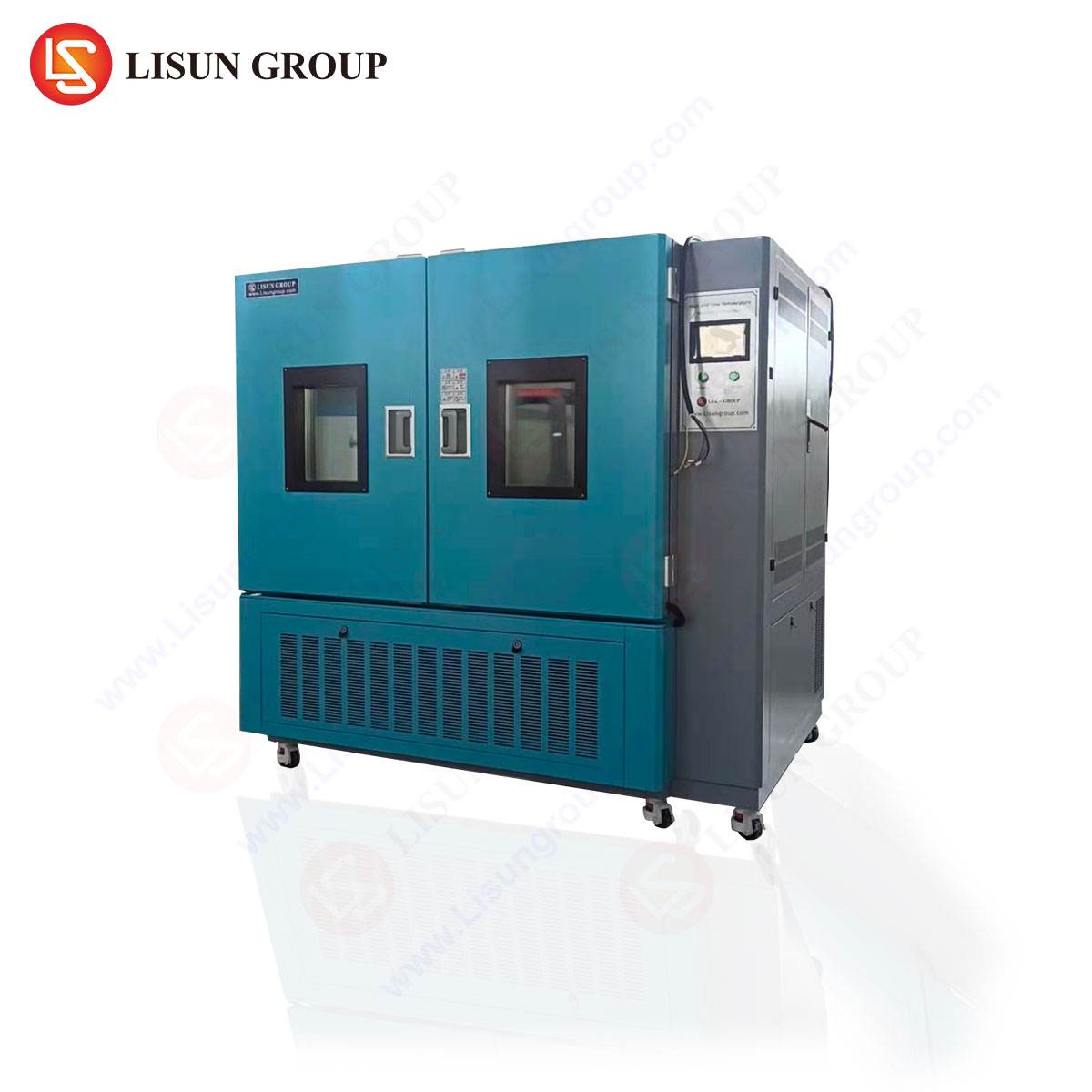
The capability to connect up to three temperature chambers to a single LEDLM-80PL system enables concurrent testing at the three required LM-80 temperature points. This parallel testing strategy reduces total qualification time by approximately 66% compared to sequential testing approaches. Each chamber can maintain independent temperature settings with ±0.5°C accuracy, while the central control system manages data acquisition from all chambers simultaneously. This configuration allows direct comparison of thermal resistance behavior across temperature conditions, facilitating more accurate Arrhenius Model parameter estimation and improving the statistical confidence of lifetime projections.
6.2 Test Duration Optimization and Data Point Selection
While IES LM-80 requires 6000 hours (approximately 8.3 months) of testing, strategic data point selection can provide interim insights. The LISUN system allows data export at 1000-hour intervals for preliminary analysis, enabling early identification of potential thermal management issues. Engineers can also implement a step-stress testing protocol where temperature is increased after stable measurements at lower temperatures, accelerating the thermal resistance characterization process. This approach, while not replacing full LM-80 compliance testing, provides valuable early-stage engineering data for design iteration before committing to the full 6000-hour qualification program.
| Test Condition | Case Temperature (°C) | Drive Current (mA) | Expected L70 (hours) | Measured Rth (°C/W) |
|---|---|---|---|---|
| Condition 1 | 55 | 350 | 72000 (projected) | 8.2 |
| Condition 2 | 85 | 350 | 36000 (projected) | 8.4 |
| Condition 3 | 105 | 350 | 18000 (projected) | 8.7 |
| Stress Condition | 85 | 700 | 14000 (projected) | 9.1 |
Table 2: Representative thermal resistance and lifetime projection data under LM-80 testing conditions
7.1 Automated Report Generation for Regulatory Submissions
LISUN’s LEDLM-80PL and LEDLM-84PL systems include comprehensive report generation software that creates IEC-compliant documentation. Reports automatically include test condition parameters, raw data tables, statistical analysis results, and Arrhenius Model projections. This documentation is formatted to meet the specific requirements of regulatory bodies, facilitating smoother certification processes. The automated reporting eliminates manual data transcription errors and ensures traceability of all measurements, supporting ISO 17025 laboratory accreditation requirements.
7.2 Data Traceability and Quality Assurance
The precision measurement requirements for thermal resistance demand robust data management protocols. The LISUN system stores all raw measurement data with timestamps, instrument identification, and calibration records. This traceability chain ensures that any subsequent audit or verification can reproduce the original measurement conditions. For third-party testing laboratories, this level of documentation is essential for maintaining accreditation and demonstrating compliance with IEC laboratory quality standards. Regular calibration verification using reference LED modules ensures ongoing measurement accuracy, with recommended verification intervals of 6 months as specified by the manufacturer.
LED thermal resistance testing represents a cornerstone of modern LED reliability assessment, directly influencing IEC compliance verification and product qualification. This article has demonstrated that precision measurement methodologies, enabled by advanced instrumentation such as the LISUN LEDLM-80PL and LEDLM-84PL systems, provide the technical foundation for accurate lumen maintenance prediction and thermal management optimization. The integration with IES LM-80, IES LM-84, TM-21, and TM-28 standards ensures that data generated through these testing programs is accepted by regulatory authorities and industry stakeholders. The 6000-hour test duration, L70/L50 metrics, and Arrhenius Model-based software deliver actionable insights into LED performance degradation mechanisms. By implementing multi-chamber testing strategies and robust data management protocols, manufacturers can significantly accelerate product development cycles while maintaining rigorous quality standards. LED thermal resistance testing precision directly correlates with the validity of lifetime projections, making this investment essential for organizations seeking competitive advantage in the global lighting market. The unique value of LISUN’s solutions lies in their comprehensive integration of photometric, electrical, and thermal measurement capabilities, enabling engineers to conduct holistic reliability assessments with minimal equipment redundancy.
Q1: How does thermal resistance measurement affect the accuracy of TM-21 lifetime projections?
A: Thermal resistance directly impacts the junction temperature calculation, which serves as the independent variable in Arrhenius Model extrapolation. An error of 5°C in junction temperature can result in approximately 20-30% error in the projected L70 lifetime due to the exponential nature of the Arrhenius relationship. Precision thermal resistance measurement (±0.5°C case temperature accuracy) ensures that the derived activation energy from multi-temperature testing is statistically robust. This accuracy is critical because TM-21 requires the 90% confidence lower bound for lifetime reporting, and any measurement uncertainty propagates through the statistical analysis. Therefore, investing in high-precision thermal measurement equipment directly improves the reliability of lifetime claims made in IEC compliance documentation.
Q2: What are the critical differences between constant current and constant temperature testing modes for thermal resistance evaluation?
A: Constant current mode maintains a fixed drive current, allowing the case temperature to vary as thermal aging changes the package’s thermal characteristics. This mode better represents real-world operating conditions where thermal management systems may degrade over time. Constant temperature mode actively adjusts the heating/cooling to maintain preset case temperature, isolating the thermal resistance behavior from ambient fluctuations. For thermal resistance calculation, constant current mode provides data at natural operating temperatures, enabling direct power dissipation calculation. Constant temperature mode facilitates comparison across different test samples at identical thermal stress levels. The dual-mode capability of the LEDLM-80PL allows engineers to choose the appropriate methodology based on whether the goal is design validation or comparative analysis.
Q3: How should engineers interpret L70 versus L50 metrics when designing for different lighting applications?
A: L70 lifetime—the time to 70% lumen maintenance—represents the threshold considered acceptable for general illumination applications such as commercial lighting, street lighting, and residential products. L50 lifetime, representing 50% lumen maintenance, applies to applications where reduced output remains functionally acceptable, including some industrial lighting, signage, and decorative installations. The selection of the appropriate metric influences both the required test duration and the statistical confidence interval calculation. TM-21 permits L70 projection up to 6 × the measured test duration (maximum 36000 hours from 6000 hours of data), while L50 projections can extend further. The LISUN software automatically computes both metrics from the measured data, enabling engineers to specify product lifetimes appropriate to their target application requirements while ensuring IEC compliance.
Q4: What factors contribute to measurement uncertainty in thermal resistance testing, and how can they be minimized?
A: Key uncertainty sources include thermocouple placement variation (±1-2°C), thermal interface material inconsistencies, ambient temperature fluctuation, and voltage/current measurement accuracy affecting power dissipation calculation. Minimizing uncertainty requires standardizing mounting torque (typically 22-25 N·cm), using thermal grease with consistent thermal conductivity, and maintaining controlled ambient conditions within the temperature chamber. The LISUN system addresses these challenges through automated mount pressure control, individual sensor calibration, and redundant temperature sensing channels. Regular verification using a test fixture with known thermal resistance helps identify systematic errors. Following these practices ensures that the reported thermal resistance values maintain measurement uncertainty below 5%, which is essential for generating confidence intervals required by IEC documentation standards.
Q5: Can the LEDLM-80PL system be used for testing mid-power and chip-on-board (COB) LED packages?
A: Yes, the LEDLM-80PL system accommodates various LED package types, including mid-power, high-power, and COB configurations, through interchangeable test fixtures and adaptable mounting systems. The system’s current range of 100 mA to 2000 mA covers typical drive conditions for most commercial LED products. For COB modules, which often operate at higher currents and generate more heat, the integrating sphere system can be equipped with appropriate sample holders and heat sink fixtures to maintain stable Tj conditions. The precision temperature control capability (±0.5°C) ensures reliable thermal resistance measurements even for packages with very low Rth values (below 1°C/W). When configuring the system for different package geometries, engineers should follow the manufacturer’s guidance for sensor placement and calibration to maintain measurement accuracy across diverse form factors.