









Abstract
Thermal shock chamber testing is a critical validation process for LED components and solid-state lighting systems, ensuring reliability under extreme temperature fluctuations. This article explores LISUN’s comprehensive thermal shock chamber testing solutions, emphasizing compliance with international standards such as IES LM-80, IES LM-84, TM-21, and TM-28. We detail the integration of the LEDLM-80PL and LEDLM-84PL optical aging test instruments, which utilize the Arrhenius Model for accelerated lumen depreciation prediction. The discussion includes dual testing modes, customizable hardware configurations, and support for up to three temperature chambers, providing engineers with robust tools for 6000-hour test cycles and L70/L50 lifespan metrics. This technical overview delivers actionable insights for enhancing LED reliability testing protocols.
1.1 The Role of Thermal Shock in LED Degradation
Thermal shock testing subjects LED samples to rapid temperature cycling, simulating harsh operational conditions that can trigger mechanical stress, solder joint fatigue, and encapsulant cracking. These stressors accelerate lumen depreciation and chromaticity shifts, which are critical failure modes in LED packages. For LED manufacturers, thermal shock testing aligns with the principles outlined in IES LM-80-15, which mandates photometric measurements over extended periods, typically 6000 hours, at controlled case temperatures. By incorporating thermal shock chambers, engineers can replicate extreme field conditions, ensuring that the LED’s lifespan projections are conservative and accurate.
1.2 LISUN’s Integrated Testing Architecture
LISUN’s thermal shock chamber testing solutions integrate seamlessly with the LEDLM-80PL and LEDLM-84PL instruments. The LEDLM-80PL is explicitly designed for LM-80 and TM-21 compliance, offering a dual-channel system that monitors current and voltage while supporting up to three connected temperature chambers. This modular design allows for simultaneous testing of multiple LED batches under distinct thermal profiles, optimizing laboratory throughput. The system’s software leverages the Arrhenius Model to extrapolate L70 and L50 metrics from accelerated stress data, reducing the need for full 6000-hour real-time tests without sacrificing accuracy. Customizable hardware configurations, including adjustable chamber sizes and temperature ranges from -40°C to +150°C, make this solution adaptable to diverse product portfolios.
2.1 IES LM-80 and TM-21: The Cornerstone of LED Lifetime Prediction
IES LM-80-15 defines the method for measuring lumen depreciation of solid-state lighting sources, specifying test durations of 3000, 6000, and 10,000 hours at controlled temperatures (typically 55°C, 85°C, and a third user-defined temperature). The data generated feeds into TM-21-19, which provides a statistical algorithm for projecting long-term lumen maintenance beyond the test window. LISUN’s LEDLM-80PL automates data acquisition at intervals per LM-80, ensuring compliance with the 1-hour minimum measurement frequency. Thermal shock pre-conditioning, when applied before LM-80 testing, evaluates the LED’s resilience to thermal cycling, a factor not explicitly covered by LM-80 but crucial for automotive and outdoor applications.
2.2 IES LM-84 and TM-28: Advanced Metrics for Integral LED Lamps
For integral LED lamps and luminaires, IES LM-84-14 introduces a streamlined testing methodology, focusing on photometric and colorimetric stability over time. TM-28-19 extends the projection methodology from TM-21 but is tailored for LM-84 data, allowing for extrapolation of L70 and L50 lifespans under specific operating conditions. The LEDLM-84PL addresses these requirements by incorporating an integrating sphere-based measurement system, which captures total flux and spectral power distribution. When combined with thermal shock chamber testing, this instrument can evaluate the impact of rapid temperature transitions on phosphor thermal quenching and driver electronics, providing a holistic view of system reliability that aligns with CIE 127 standards for LED measurement.
3.1 LEDLM-80PL vs. LEDLM-84PL: Comparative Analysis
The choice between the LEDLM-80PL and LEDLM-84PL depends on the application scope. The LEDLM-80PL is optimized for component-level testing (LED packages, arrays, and modules), while the LEDLM-84PL focuses on integral lamps and luminaires. The table below highlights key specifications that impact thermal shock testing integration.
| Specification | LEDLM-80PL | LEDLM-84PL |
|---|---|---|
| Compliant Standards | IES LM-80, TM-21 | IES LM-84, TM-28 |
| Test Duration Support | Up to 6000+ hours | Up to 6000+ hours |
| Temperature Chambers | Up to 3 connected | Up to 3 connected |
| Measurement Method | Goniophotometer or Integrating Sphere | Integrating Sphere (2m or 3m options) |
| Output Metrics | Lumen Depreciation, CCT Shift, L70/L50 | Lumen Depreciation, CRI Shift, L70/L50 |
| Data Acquisition Interval | ≥1 hour (per LM-80) | ≥1 hour (per LM-84) |
3.2 Arrhenius Model-Based Software and Dual Testing Modes
LISUN’s proprietary software simplifies complex reliability calculations by embedding the Arrhenius Model, which correlates test temperature with acceleration factors. In thermal shock chamber testing, the software can automatically calculate the activation energy (Ea) from multi-temperature data, enabling precise extrapolation of lumen maintenance at standard operating temperatures. Dual testing modes—constant current and constant voltage—allow engineers to mimic real-driver conditions or isolate LED chip degradation. For example, a constant current mode at 350 mA with a case temperature of 85°C, combined with thermal cycling from -40°C to +125°C, can reveal early failures in wire bonds that would otherwise go undetected in isothermal tests.
4.1 Sample Preparation and Chamber Configuration
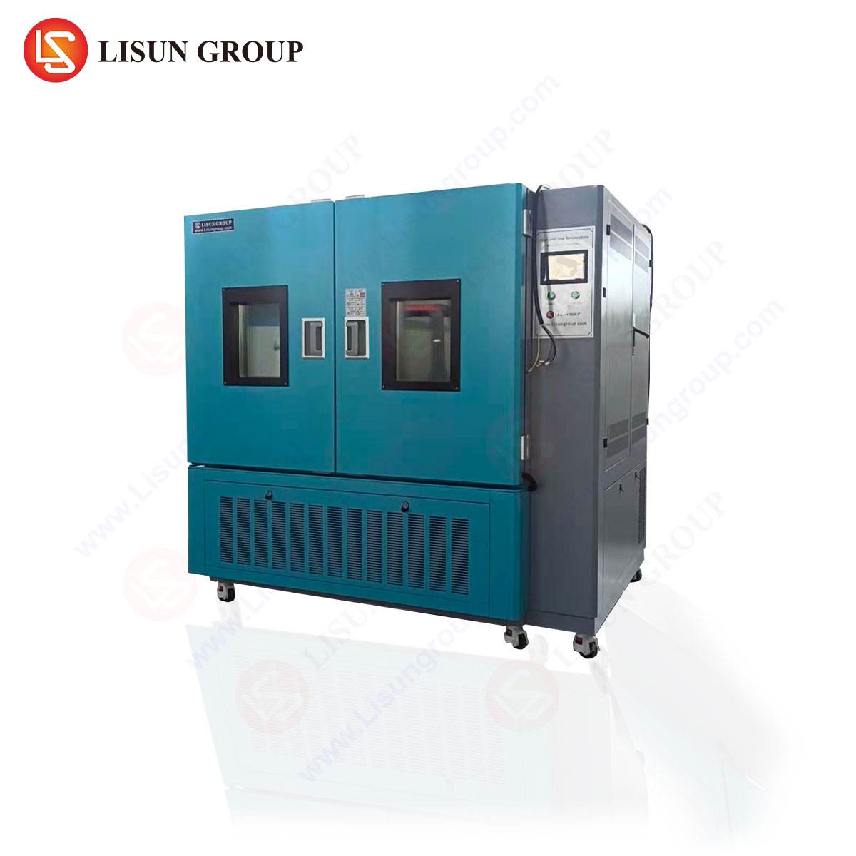
Effective thermal shock testing requires meticulous sample preparation. Engineers must mount LEDs on thermal interface materials with low thermal resistance to ensure accurate case temperature control. LISUN chambers support programmable thermal cycling profiles, including dwell times, ramp rates (up to 50°C/min), and cycle counts. For LM-80 compliance, the thermal shock phase is typically performed as a pre-test stressor, followed by steady-state aging in the LEDLM-80PL. The system’s ability to connect up to three chambers enables parallel testing under different thermal shock severities, such as 500 cycles at -20°C to +100°C for consumer grade and 1000 cycles at -40°C to +125°C for automotive grade.
4.2 Data Collection and L70/L50 Extrapolation
Data from thermal shock testing is logged automatically, capturing luminous flux, forward voltage, and correlated color temperature (CCT) at user-defined intervals. The software applies TM-21’s nonlinear regression to project L70 (time to 70% lumen maintenance) and L50 (time to 50%), with confidence intervals of 90%. For instance, a 6000-hour LM-80 test dataset, combined with an acceleration factor of 4 from thermal shock, can yield a projected L70 of over 50,000 hours. This methodology aligns with IES LM-79-19 for electrical and photometric measurements, ensuring that the input data for projection is spectrally accurate and traceable.
5.1 Integrating Sphere Measurements in the LEDLM-84PL
Thermal shock can induce color shifts due to phosphor degradation or binder decomposition in LED packages. The LEDLM-84PL utilizes a 2-meter integrating sphere with a spectral range of 350-1100 nm, enabling precise measurement of chromaticity coordinates per CIE 084. By measuring spectral power distribution before, during, and after thermal shock cycles, engineers can quantify Δu’v’ shifts, a critical parameter for lighting quality. The system’s software flags samples exceeding thresholds established by TM-28, such as Δu’v’ > 0.003 for indoor lighting applications.
5.2 Correlating Thermal Shock with CIE 127 and CIE 70 Standards
CIE 127 provides guidelines for LED measurement, including far-field and near-field conditions within an integrating sphere. When thermal shock causes changes in the LED’s beam pattern, adherence to CIE 127 ensures that measurements remain reproducible. Additionally, CIE 70 outlines the assessment of light distribution through goniophotometry, which is relevant for luminaires undergoing thermal cycling. LISUN’s comprehensive solution allows engineers to combine goniophotometric data (for intensity distribution) with integrating sphere data (for flux and color), providing a complete reliability profile that is defensible in third-party regulatory audits.
6.1 Automotive and Aerospace Applications
In automotive exterior lighting, LEDs must withstand extreme temperature gradients under the hood or near exhaust systems. LISUN’s customizable chambers can be configured with higher temperature ceilings (+150°C) and faster transition times to mimic thermal shock conditions per AEC-Q102 standards. The LEDLM-80PL’s support for multiple chamber connections facilitates long-term stability testing across three different temperature settings simultaneously, such as 65°C, 85°C, and 105°C, with thermal shock pre-conditioning, accelerating defect discovery and reducing time-to-market.
6.2 Integration with Third-Party Data Management Systems
For laboratories operating under ISO 17025 accreditation, data integrity is paramount. LISUN’s software exports data in XML, CSV, and Excel formats, compatible with Laboratory Information Management Systems (LIMS). This ensures traceability for audits and simplifies reporting for LM-80 and TM-21 submissions. The customizable hardware options, such as additional thermocouple inputs and adjustable sample trays, allow the system to accommodate various form factors, from Chip-on-Board (COB) modules to flexible LED strips, making the solution versatile for testing service providers.
7.1 Optimizing Test Schedules with Dual Modes
To maximize laboratory throughput, engineers can use the dual testing modes strategically. The constant voltage mode is ideal for detecting early solder joint failures, as it exposes resistance increases, while constant current mode is better suited for evaluating phosphor degradation. Running both modes concurrently in separate chambers (up to three) allows for a matrix of conditions—e.g., 2 chambers at constant current with different temperatures and 1 chamber at constant voltage with thermal shock cycling. This approach yields comprehensive data within the 6000-hour test window.
7.2 Avoiding Common Pitfalls in Thermal Shock Testing
A common pitfall is insufficient dwell time at extreme temperatures, leading to incomplete thermal equilibrium and skewed results. ISUN’s software enforces minimum dwell times based on sample thermal mass, with a default of 30 minutes or until the case temperature stabilizes within ±2°C. Additionally, engineers must account for LED self-heating; the case temperature (Tc) should be monitored via the instrument’s thermocouple channels to ensure that the intended test temperature is consistent with the junction temperature (Tj) assumptions in the Arrhenius Model. Proper calibration of the integrating sphere and goniophotometer, as per IES LM-79-19, is also crucial to maintaining the ±2% luminous flux measurement uncertainty.
LISUN’s thermal shock chamber testing solutions provide a robust, standards-compliant framework for validating LED reliability under extreme thermal stress. By integrating the LEDLM-80PL and LEDLM-84PL instruments, engineers can conduct comprehensive testing that aligns with IES LM-80, IES LM-84, TM-21, and TM-28, while leveraging the Arrhenius Model for accelerated lifetime predictions. The support for up to three temperature chambers, customizable hardware, and dual testing modes ensures flexibility across automotive, aerospace, and general lighting applications. The 6000-hour test durations and L70/L50 metrics derived from these systems offer defensible data for regulatory submissions and quality assurance. For LED manufacturers aiming to enhance product durability, LISUN’s solutions bridge the gap between laboratory stress testing and real-world performance, delivering the precision and efficiency required in today’s competitive marketplace.
Q1: How does thermal shock chamber testing integrate with IES LM-80 lumen maintenance tests?
A: Thermal shock testing serves as a pre-conditioning stressor before the standard LM-80 aging test. Per IES LM-80-15, the aging test lasts 6000 hours at controlled case temperatures (e.g., 55°C, 85°C, and a third temperature). By subjecting samples to rapid thermal cycling (e.g., 500-1000 cycles from -40°C to +125°C), engineers can identify mechanical and solder joint weaknesses early. After this pre-stress, the LEDs are placed in the LISUN LEDLM-80PL for continuous lumen depreciation tracking. The software then applies TM-21 extrapolation to predict L70/L50 lifespans, combining the mechanical stress impact with thermal aging. This dual-phase approach ensures that the projected lifetime is conservative and reflects real-world field conditions, especially for outdoor or automotive applications.
Q2: What are the key differences between the LEDLM-80PL and LEDLM-84PL in testing scenarios?
A: The LEDLM-80PL is tailored for component-level testing per IES LM-80, using either a goniophotometer or an integrating sphere, and is ideal for LED packages, arrays, and modules. It supports up to three temperature chambers, enabling multi-temperature ageing. In contrast, the LEDLM-84PL is designed for integral LED lamps and luminaires, aligning with IES LM-84. It employs a larger integrating sphere (2m or 3m) to capture total flux and color metrics for complete systems, including drivers. For thermal shock testing, the LEDLM-80PL is typically used for the LED emitter, while the LEDLM-84PL evaluates the entire luminaire housing’s resilience. Both systems support 6000-hour tests and use Arrhenius-based software for L70/L50 projections, but their sample size and measurement metrics differ significantly.
Q3: How does the Arrhenius Model improve the accuracy of L70/L50 predictions from thermal shock data?
A: The Arrhenius Model establishes a linear relationship between temperature and degradation rates, quantified by activation energy (Ea). Thermal shock testing introduces a distribution of test temperatures, allowing LISUN’s software to calculate Ea from at least two different temperature datasets. For example, if testing at 85°C and 105°C with thermal cycling stress, the software determines how much faster the LED degrades at the higher temperature, then extrapolates this to the nominal operating temperature (e.g., 45°C). This yields highly accurate L70 (70% lumen maintenance) and L50 (50% lumen maintenance) years, often projecting beyond 50,000 hours. Without the Arrhenius Model, engineers would rely solely on real-time aging, which is impractical for extended lifespans. The model, combined with TM-21’s statistical algorithms, provides a 90% confidence lower bound for the projected lifetime.
Q4: Can LISUN’s thermal shock chambers simulate humidity or other environmental factors alongside temperature cycling?
A: Yes, LISUN offers customizable chambers that can incorporate humidity control, typically maintaining relative humidity from 20% to 98% within a temperature range of +20°C to +85°C. This is particularly relevant for LED applications in damp locations or outdoor fixtures. However, for high-temperature thermal shock (e.g., above +100°C), humidity control is usually deactivated to prevent condensation. The chambers can also be configured with optional UV irradiation for accelerated weathering, although this is separate from standard thermal shock profiles. The user-defined programming allows for complex sequences, such as thermal cycling followed by a humidity soak, to mimic IP-rated fixture conditions, providing a more comprehensive reliability assessment.
Q5: What is the recommended sample size for thermal shock testing to ensure statistically valid L70/L50 results?
A: For statistical significance per IES LM-80 and TM-21, a minimum of 20 samples per test condition is recommended. LISUN’s chambers are sized to accommodate 20-50 LED modules or lamps per cycle, depending on form factor. In thermal shock testing, we advise using 30 samples per temperature chamber to account for potential early failures. For example, if you test 30 samples at 85°C and 30 at 105°C, plus a control group, the software can perform outlier analysis and construct the TM-21 projection curve. If the application is high-risk, such as automotive headlamps, a larger sample size (50+) is advisable to achieve a tighter 90% confidence interval for the L70 prediction. Proper sample preparation, including thermal interface material application, is critical to ensure each sample’s case temperature matches the target setpoint.