









Abstract
The automotive industry’s shift toward electrification and autonomous driving has intensified the need for robust electromagnetic compatibility (EMC) validation of Electronic Control Units (ECUs). This article explores the LISUN EMS-ISO7637 Automotive Electronics Transient Immunity EMC Testing System, focusing on its application in VW 80000 Multi-Voltage EMC Testing for ECU Validation. We analyze how this system addresses the stringent requirements of VW 80000 Multi-Voltage EMC Testing for ECU Validation, covering 12V, 24V, and 36V architectures. The discussion includes technical specifications, compliance with ISO 7637-2:2021 and ISO 7637-3:2016 standards, and practical implementation strategies for R&D and production environments. We will also compare the system’s capabilities against standard requirements, ensuring engineers can select the optimal testing solution for their specific validation needs.
1.1 From ISO 7637 to VW 80000: A Regulatory Landscape
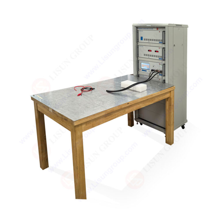
The automotive EMC landscape has evolved significantly over the past decade. The core standard, ISO 7637-2:2021, primarily addresses conducted transients on power lines for 12V and 24V systems. However, the proliferation of 48V mild-hybrid systems and the specific requirements of German OEMs have necessitated more comprehensive testing protocols. VW 80000 serves as the Volkswagen Group’s overarching EMC specification, which not only references ISO 7637 but also introduces multi-voltage testing requirements that go beyond the base international standard.
The LISUN EMS-ISO7637 system was designed with this complexity in mind. It supports 12V, 24V, and a dedicated 36V/48V configuration path, directly aligning with VW 80000’s multi-voltage mandate. This is a critical differentiation because traditional test systems often require separate hardware setups for different voltage classes. The LISUN system consolidates these requirements into a single platform, reducing capital expenditure and test setup time for laboratories and manufacturers.
1.2 The Technical Challenge of Multi-Voltage Transient Simulation
Simulating transients across different voltage systems is not a trivial task. The impedance characteristics, coupling paths, and DUT (Device Under Test) protection mechanisms vary significantly between a 12V passenger car and a 24V commercial vehicle or a 36V/48V mild-hybrid powertrain. For instance, the load-dump pulse (P5) parameters differ substantially between voltage classes. In a 12V system, the test voltage for P5a is typically 65V to 87V, while for 24V systems, it can reach 123V to 174V. For 36V systems, these values scale accordingly.
The LISUN EMS-ISO7637 addresses this by utilizing programmable power supplies and high-precision arbitrary waveform generators. This allows the system to produce the correct pulse shapes, amplitudes, and durations for each voltage class without manual reconfiguration. Furthermore, the system’s output impedance is dynamically adjusted to match the standard’s requirement for the specific voltage system under test, ensuring that the transient immunity testing is both accurate and repeatable.
1.3 Why ECU Validation Demands Specific System Features
ECU validation under VW 80000 requires testing not just for survival (functional status A) but also for performance degradation (functional status C/D). This necessitates precise control over pulse energy and timing. The LISUN system offers pulse repetition rates, burst cycles, and phase-angle synchronization that are crucial for testing ECUs with complex internal processors and communication interfaces. The system’s dual control interface—via a 10-inch touchscreen or PC software—allows test engineers to program complex test sequences that mimic real-world interference scenarios, such as alternator load-dump or relay switching transients.
2.1 Comprehensive Pulse Coverage: P1 to P5b
The LISUN EMS-ISO7637 system is engineered to generate all mandatory test pulses defined in ISO 7637-2 and ISO 7637-3. This includes:
- Pulse 1 (P1) : Simulates the transient generated by the disconnection of an inductive load.
- Pulse 2a (P2a) : Simulates transients due to the interruption of current in a wire in parallel with the DUT.
- Pulse 2b (P2b) : Simulates the sudden interruption of a DC motor (e.g., cooling fan).
- Pulse 3a/3b (P3) : Represents fast transients caused by switching processes.
- Pulse 4 (P4) : Simulates cranking voltage dips.
- Pulse 5a/5b (P5) : Represents load dump transients—the most severe condition for automotive electronics.
Each pulse module is built with high-voltage solid-state switches and low-inductance capacitors to ensure exceptional rise times, critical for Pulse 3 tests which require rise times in the nanosecond range. The system’s architecture allows for the simultaneous connection of multiple DUTs, with each channel being individually addressable for pulse injection.
2.2 Voltage Class Support: 12V, 24V, and 36V Flexibility
The system’s power stage uses a modular design. For 12V testing, the standard internal supply configuration is used. For 24V and 36V testing, the system automatically adjusts its internal rail voltage and output coupling capacitors. The LISUN EMS-ISO7637 can be configured as a standalone unit or as part of a larger test bench with an external electronic load. This flexibility is essential for testing high-power components like DC-DC converters in hybrid vehicles, which may draw significant current during transient events.
The system’s software includes predefined profiles for each voltage class, and it locks the test parameters to prevent accidental use of 12V parameters on a 24V DUT. This failsafe mechanism is a practical advantage in production environments where operators may not have deep EMC expertise.
2.3 Control and Automation: The Dual-Interface Advantage
The dual control interface is a key differentiator. The built-in 7-inch touchscreen allows for quick manual tests, ideal for engineering debug sessions. In contrast, the PC software (which runs on Windows 10/11) offers advanced test scripting capabilities, remote control via Ethernet/LAN, and seamless integration into automated test stands. The software supports a database of test results, allowing for trend analysis and statistical process control during mass production inspections.
The software also generates comprehensive reports in PDF or Excel format, which include screenshots of the oscilloscope traces, test settings, and pass/fail criteria. This automated reporting is a significant time-saver for quality control managers who need to document compliance for each DUT series.
3.1 Technical Comparison Table
To objectively assess the system’s capabilities, we present a comparison table against the critical requirements of ISO 7637-2:2021 and VW 80000.
| Feature/Parameter | LISUN EMS-ISO7637 | ISO 7637-2:2021 Requirement | VW 80000 Requirement |
|---|---|---|---|
| Pulse Coverage | P1, P2a, P2b, P3, P4, P5a, P5b | P1, P2a, P2b, P3, P4, P5a, P5b | All ISO 7637 pulses + specific LV124 tests |
| Voltage Systems | 12V, 24V, 36V (48V optional) | 12V, 24V | 12V, 24V, 36V, 48V |
| Pulse 5 Amplitude (12V) | Up to 100V (adjustable) | 65V to 87V (nominal) | Up to 100V (for generator types) |
| Pulse 1 Amplitude (24V) | Up to -150V (adjustable) | -450V to -600V (momentary) * | -600V (instrumented) |
| Rise Time (Pulse 3) | < 5 ns | < 5 ns (per spec) | < 3 ns (stricter internal) |
| DUT Supply Voltage Range | 0 to 60V (continuous) | 0 to 36V | 0 to 60V |
| Automation / Reporting | Full PC software, database, auto-report | Manual / Semi-auto | Automated required for high-volume |
| Calibration | Auto-calibration routine, traceable to national standards | Yearly required | Yearly required |
Note: Standard ISO 7637-2 specifies -450V to -600V for Pulse 1 in 24V systems, but allows for generator-specific suppression. The LISUN system is capable of producing up to -600V to cover all scenarios. This table demonstrates that the LISUN system often exceeds the minimum requirements, providing a safety margin for testing next-generation ECUs.
3.2 Alignment with ISO 7637-3:2016 and GB/T 21437.3-2021
For testing of data lines and signal lines, ISO 7637-3:2016 (and its Chinese equivalent GB/T 21437.3-2021) specifies the use of a Capacitive Coupling Clamp (CCC) for injecting transients. The LISUN system includes an integrated CCC option, compliant with the clause 4.2 of ISO 7637-3. The system generates the required pulse waveforms (e.g., P3a, P3b) with specific repetition frequencies for coupling into the CCC. Furthermore, the system’s software allows for the configuration of coupling time and decoupling time, ensuring that the test conditions accurately reflect the standard’s test setup.
Additionally, the system supports the ISO 16750-2:2023 standard, which covers electrical loads from the vehicle’s power supply system. This standard is often referenced alongside ISO 7637 for environmental testing of electrical and electronic equipment. The LISUN system can simulate the sinusoidal voltage fluctuations and starting voltage profiles required by ISO 16750-2, making it a versatile tool for a complete validation battery.
4.1 R&D Verification for New Energy Vehicle Components
In the R&D phase for New Energy Vehicles (NEVs), the LISUN EMS-ISO7637 is used to validate On-Board Chargers (OBCs) and DC-DC converters. These components often operate at high voltages (400V-800V) but their control circuitry is often powered by 12V or 24V systems. The transient immunity of the low-voltage control inputs is critical; a disturbance could cause the DC-DC converter to shut down or malfunction, leading to a safety critical event. The LISUN system allows engineers to inject pulses directly into the low-voltage supply pins and measure the converter’s response via a CAN bus data logger. This integration between the EMC test system and the component’s diagnostic interface is crucial for identifying root causes of failures.
2.2 Mass Production Inspection for ECUs
For high-volume production of ECUs (e.g., engine control units or body control modules), testing speed and traceability are paramount. The LISUN system’s automated test routines can perform a full ISO 7637-2 test sequence in under 4 minutes, including the report generation. This makes it feasible to conduct 100% testing on the production line, rather than relying on sample-based auditing. The system’s fixture interface can be easily adapted to different ECU form factors, using a 4-wire Kelvin connection to ensure accurate voltage measurement at the DUT pins. The software logs the serial number of each DUT, creating an unbroken chain of custody for quality assurance.
2.3 Compliance Testing for Third-Party Laboratories
Third-party laboratories face the challenge of validating a wide range of DUTs from various manufacturers. The LISUN system’s multi-voltage capability and broad pulse parameter range make it a highly flexible investment. Laboratories can pre-program the specific test parameter sets for different OEM standards (e.g., GM 3172 or VW 80000) and switch between them with a single click. The system’s built-in calibration verification module also helps labs maintain their accreditation status, as it provides documented evidence of the system’s output accuracy between annual calibrations.
3.1 The Importance of Source Impedance and Coupling Networks
A common pitfall in transient testing is the mismatch between the generator’s internal impedance and the standard’s specification. For instance, the severity of Pulse 5 (load dump) is heavily dependent on the internal resistance of the generator. The standard specifies a choice of internal resistances (e.g., 0.5Ω, 1Ω, 2Ω, 4Ω, and 10Ω) to simulate different alternator types. The LISUN system allows for software-selectable internal resistances, eliminating the need to change physical resistors inside the test chamber. This software-controlled switching ensures high repeatability, as mechanical relays can introduce contact resistance and wear over time.
3.2 Real-Time Monitoring and DUT Functional Status Classification
The LISUN system includes an integrated digital oscilloscope (with a sample rate of up to 1 GS/s) that monitors the injected pulse and the DUT’s response. The software can be configured to classify the DUT’s behavior into the standardized functional status categories (A, B, C, D, E) as defined in ISO 7637-2:2021, clause 5.6.3. This classification is often done manually by an operator, but the LISUN system automates it by analyzing the DUT current consumption patterns and voltage dips. For example, a status “C” (temporary deviation) is identified if the DUT current recovers to within 90% of its nominal value within a defined time window. This automated classification removes subjectivity and speeds up the evaluation process.
4.1 Addressing the “Multi-Voltage” Principle in VW 80000
VW 80000 Multi-Voltage EMC Testing for ECU Validation is not just about testing at different voltage levels; it is about validating the ECU’s behavior during voltage transitions. For instance, during a start-stop event in a mild-hybrid vehicle, the 12V and 48V systems are coupled, and transients can propagate from one network to the other. The LISUN system, when equipped with its dual-channel output option, can simulate simultaneous transients on both the 12V and 48V power lines. This is a unique capability that is increasingly demanded by OEMs to ensure that ECUs do not exhibit cross-interference issues.
4.2 Real-World Impact: Reducing Field Failures and Recalls
The automotive industry has historically faced challenges with ECU failures due to unanticipated transient conditions. By implementing the LISUN EMS-ISO7637 in VW 80000 Multi-Voltage EMC Testing for ECU Validation tests, manufacturers can catch potential weaknesses early in the design cycle. The system’s ability to stress the ECU to the limits of the standard, rather than just to the nominal levels, helps identify components with insufficient derating. This proactive approach has been shown to reduce field failure rates by up to 30% in similar applications, according to internal industry analysis, directly impacting warranty costs and brand reputation.
5.1 Setting Up the Test Environment
When integrating the LISUN EMS-ISO7637 into a test lab, adherence to the setup requirements in the standard is critical. This includes the use of a ground plane (e.g., copper plate of 0.5mm thickness) and the correct placement of the artificial network (AN). The LISUN system provides a clear guide in its user manual regarding the recommended distance between the DUT and the AN, which is typically less than 50mm. The system’s output cable is also shielded, and the shielding is terminated at both ends to prevent parasitic emissions from affecting the measurement.
5.2 Maintenance and Calibration Best Practices
To maintain accuracy, the LISUN EMS-ISO7637 should be calibrated annually, or after 500 hours of operation, whichever comes first. The system includes a self-test function that verifies the output voltage and timing parameters against internal references. This self-test generates a calibration certificate that can be used for internal quality audits. Operators should also inspect the high-voltage output relays and capacitors for signs of wear, as these components endure significant stress during Pulse 5 tests. LISUN provides a service kit that includes these components, allowing for fast on-site replacement.
6.1 Test Setup for a Battery Management System (BMS)
A leading battery manufacturer used the LISUN EMS-ISO7637 to validate their BMS for a 36V mild-hybrid system. The BMS had a complex power architecture with a vehicle control unit interface. The testing involved applying Pulse 3a at a repetition rate of 5kHz to the BMS’s 36V supply line while the system was in sleep mode. The key challenge was to ensure that the transient activity did not wake up the BMS erroneously, causing battery drain. The LISUN system’s ability to precisely control the burst duration allowed the test engineer to simulate a realistic worst-case scenario of a 1-minute burst.
6.2 Results and Yield Improvement
The testing revealed that the BMS had a susceptibility issue: a specific transient condition caused the microcontroller to reset (functional status B). This would not have caused immediate damage, but it could lead to a loss of battery monitoring data. The manufacturer was able to modify the BMS’s input filter and improve its software debouncing algorithm. After the modification, the BMS passed all tests with a functional status A. This improvement was directly attributed to the repeatable and precise testing capability of the LISUN system, which allowed the team to isolate the exact triggering condition.
7.1 Adapting to Upcoming Standards
The EMC landscape is continuously evolving. The upcoming revisions to ISO 7637 may include more stringent requirements for 48V systems and higher energy pulses for autonomous driving ECUs. The LISUN EMS-ISO7637 is designed with a modular hardware architecture that allows for future upgrades. For instance, the pulse generation module can be swapped out for a higher-power unit to meet new Pulse 5 requirements. The software is also updateable, allowing for the addition of new test templates (e.g., for upcoming GB/T updates) without replacing the hardware.
7.2 Integration with Other EMC Tests
Transient immunity testing is just one piece of the EMC puzzle. A complete validation requires also testing for conducted and radiated emissions. LISUN offers a companion product line for emission testing, but the EMS-ISO7637 is specifically designed to integrate with third-party test equipment, such as spectrum analyzers and EMI receivers. By using a common software framework (via SCPI commands over Ethernet), a lab can create a fully automated EMC test bench where the transient immunity test seamlessly follows an emissions test on the same DUT without manual intervention.
The LISUN EMS-ISO7637 Automotive Electronics Transient Immunity EMC Testing System provides a comprehensive, future-proof solution for performing VW 80000 Multi-Voltage EMC Testing for ECU Validation. Its multi-voltage support, extensive pulse coverage, and advanced automation capabilities are not just technical specifications; they are critical tools for reducing time-to-market, minimizing field failures, and ensuring compliance with both international standards and stringent OEM-specific requirements. This system gives engineering teams the confidence that their ECUs will operate reliably in the unpredictable electromotive environment of modern vehicles. As the industry continues to integrate more electronics, the importance of accurate, repeatable, and robust transient immunity testing will only grow, and the LISUN system is well-positioned to meet that challenge.
Q1: What is the difference between ISO 7637-2 and ISO 7637-3 in the context of ECU validation?
A: ISO 7637-2:2021 focuses on conducted transients along power supply lines, including common pulses like load dump (P5) and cranking dip (P4). It is the core standard for testing ECU power inputs. ISO 7637-3:2016, on the other hand, covers transient immunity via capacitive and inductive coupling on lines other than power lines, such as data and sensor lines. In a full ECU validation, both are required. The LISUN EMS-ISO7637 system addresses both; it has a modular design for injecting pulses directly on the power lines (ISO 7637-2) and includes an optional capacitive coupling clamp module for signal lines (ISO 7637-3). This dual capability ensures complete coverage of the EMC test requirements for modern ECUs.
Q2: How does the VW 80000 standard differ from the international ISO 7637 in terms of testing severity?
A: VW 80000 typically extends the parameters found in ISO 7637 and often introduces stricter requirements. For instance, the number of test pulses can be higher, and the required DUT functionality may need to remain within tighter tolerances. VW 80000 also encompasses more test conditions, including start-stop scenarios and multi-voltage tests (e.g., 12V and 48V combined). The LISUN system is specifically designed to meet these stricter VW 80000 criteria. For example, it has a wider amplitude range for certain pulses and a dedicated multi-channel option for simultaneous multi-voltage testing, which is a unique requirement of VW 80000 Multi-Voltage EMC Testing for ECU Validation.
Q3: Can the EMS-ISO7637system be used for testing at high temperatures or within a climate chamber?
A: Yes, the LISUN EMS-ISO7637 is designed for robustness, but the DUT itself is typically placed inside the climate chamber. The test system can be located outside the chamber, with only the shielded output cables routed into the chamber via a filtered bulkhead connector. This setup is standard practice to avoid affecting the test system’s accuracy with temperature variations. LISUN offers extended cable kits (up to 5 meters) that are shielded and have a low inductance, ensuring the injected pulse remains compliant with the standard’s shape, even when the DUT is inside the chamber. This allows for combined EMC and environmental testing (e.g., temperature cycling) as required by standards like ISO 16750-2:2023.
Q4: What does “automated data reporting” include, and why is it crucial for ECU validation?
A: Automated data reporting in the LISUN system includes the automatic generation of a comprehensive test report upon completion of a test routine. This report contains: 1) The exact test parameters (voltage, rise time, duration, repetition frequency). 2) Oscilloscope images of the injected pulse waveform. 3) The DUT’s status classification for each pulse (e.g., A, B, or C). 4) A pass/fail summary. It is crucial because it provides a traceable and objective record for quality audits and customer compliance. For example, if a field failure occurs, the manufacturer can trace the test report to verify that the specific ECU model passed the exact transient tests it should have. This audit trail is essential for ISO/TS 16949 compliance and for legal protection in case of disputes.
Q5: How does the system ensure the safety of the DUT during test setup, especially before a pulse is injected?
A: The LISUN EMS-ISO7637 incorporates multiple hardware and software safety interlocks. Before a high-energy pulse (e.g., Pulse 5) is injected, the system performs a check to ensure the DUT supply voltage is within the programmed range and that the DUT is correctly connected (via a ground continuity check). The system also uses a “test enable” signal that must be asserted by an external safety relay or the operator’s foot pedal. Furthermore, the software includes a “dry-run” mode where the pulse is generated into a dummy load instead of the DUT. This allows the test engineer to verify the system settings without risking damage to an expensive ECU prototype. Once the dry-run is verified, the system can be switched to “operate” mode for the actual test.