








Abstract
Selecting the appropriate load cabinet for switch testing is a critical decision that directly impacts the accuracy, repeatability, and compliance of electrical accessory evaluations. The LISUN DFX series Externally Ballasted Fluorescent Lamp Test Load Cabinet provides a sophisticated solution for simulating real-world electrical loads during durability and safety testing of switches, lamps, and other accessories. This comprehensive guide examines the technical specifications, standard compliance, and selection criteria for the DFX series, including the DFX-20, DFX-20-3CH, DFX-40, DFX-60, and DFX-80 models. By understanding load simulation principles, power factor adjustment capabilities, and international standard requirements, engineers can make informed decisions when implementing a load test cabinet for their testing laboratories.
1.1 The Physics of Electrical Load Simulation
Switch testing requires precise replication of real-world operating conditions to validate product reliability and safety. The fundamental challenge lies in simulating the complex electrical characteristics of actual loads, particularly those involving fluorescent lamps with external ballasts. These loads exhibit non-linear voltage-current relationships, significant reactive power components, and inrush current behaviors that cannot be accurately replicated using simple resistive elements alone.
The LISUN DFX series addresses this complexity by incorporating adjustable resistive and inductive components that model the impedance characteristics of externally ballasted fluorescent lighting systems. This dual-element approach enables testing engineers to replicate both the steady-state operating conditions and the transient switching stresses that switches experience during normal service.
1.2 Core Parameters for Load Test Cabinet Configuration
Three fundamental parameters govern the configuration of any load test cabinet: voltage, current, and power factor. The DFX series operates at input voltages up to 480VAC, with current handling capabilities ranging from 20A to 80A depending on the model selected. Power factor adjustment spans from 0.3 to 1.0, allowing precise replication of inductive load characteristics typical of ballasted lighting systems.
The power factor resolution of 0.01 provides fine-grained control over the reactive-to-real power ratio, essential for tests that assess switch contacts’ ability to interrupt inductive circuits without excessive arcing or premature wear. This parameter directly influences test repeatability and correlation with field performance data.
2.1 Load Circuit Design and Component Specifications
The DFX series employs high-precision inductive coils constructed with oxygen-free copper windings and low-loss magnetic cores to achieve the required inductance values with minimal temperature drift. Each load circuit incorporates switching-grade resistors rated for continuous operation at maximum rated current, ensuring thermal stability during extended endurance tests.
Capacitance compensation networks within the unit maintain power factor stability across the operational current range. The modular construction allows rapid reconfiguration between different load profiles without requiring recalibration, substantially reducing test setup time for laboratories managing diverse product evaluation schedules.
2.2 Safety and Protection Systems
Integrated thermal protection systems monitor winding temperature and automatically de-rate output when operating near maximum ratings. Overcurrent relays provide instantaneous protection against fault conditions, while the enclosure design meets IP20 ingress protection requirements for laboratory environments. Built-in voltage and current monitoring terminals permit direct connection to external measurement instruments without compromising circuit integrity.
The DFX-20-3CH model provides three independent channels, each rated at 20A, enabling simultaneous testing of multiple switches under identical or different load conditions. This configuration maximizes throughput for certification laboratories while maintaining test independence across channels.
3.1 IEC Standards Framework
The DFX series load cabinets support compliance testing against multiple international standards, including:
- IEC 60669-1 Clause 19.2 detailing endurance testing requirements for switches with fluorescent loads
- IEC 60884-1 Clause 20 governing plug and socket-outlet durability testing
- IEC 61058-1 covering switches for appliances
- IEC 60669-2-1 for particular requirements of electronic switches
Each standard specifies distinct load parameters, switching rates, and endurance cycles that must be precisely replicated for valid certification results. The DFX series enables exact parameter matching through its fine adjustment capabilities and digital metering integration.
3.2 Load Configuration Requirements by Standard
Table 1 presents a comparison of minimum load requirements across key standards and the corresponding LISUN DFX configurations:
| Standard | Test Current | Power Factor | Voltage | Required Cycles | LISUN Model |
|---|---|---|---|---|---|
| IEC 60669-1 19.2 | 1.0 × rated current | 0.6 ± 0.05 | 1.1 × rated voltage | 50,000 | DFX-20 |
| IEC 60884-1 20 | 0.8 × rated current | 0.6 ± 0.05 | Rated voltage | 10,000 | DFX-20-3CH |
| IEC 61058-1 | Rated current max | 0.75 ± 0.05 | Rated voltage | Varies by category | DFX-40 |
| IEC 60669-2-1 | 1.25 × rated current | 0.5 ± 0.05 | 1.1 × rated voltage | Varies by category | DFX-60 |
The DFX-80 model serves high-current applications requiring up to 80A continuous load capability, addressing the needs of industrial-rated switches and heavy-duty control devices.
4.1 Specification Comparison Across DFX Models
Table 2 provides technical specifications for selecting the appropriate load test cabinet:
| Parameter | DFX-20 | DFX-20-3CH | DFX-40 | DFX-60 | DFX-80 |
|---|---|---|---|---|---|
| Current Range (A) | 0-20 | 0-20/channel | 0-40 | 0-60 | 0-80 |
| Channel Count | 1 | 3 | 1 | 1 | 1 |
| Max Input Voltage (VAC) | 250 | 250/channel | 250V phase or 480V L-L | 250V phase or 480V L-L | 480V L-L |
| Power Factor Range | 0.3-1.0 | 0.3-1.0 | 0.3-1.0 | 0.3-1.0 | 0.3-1.0 |
| Power Factor Resolution | 0.01 | 0.01 | 0.01 | 0.01 | 0.01 |
| Frequency (Hz) | 50/60 | 50/60 | 50/60 | 50/60 | 50/60 |
| Load Capacitance (μF) | 0-100 | 0-100/channel | 0-200 | 0-200 | 0-300 |
| Measurement Accuracy (%) | ±0.5 | ±0.5 | ±0.5 | ±0.5 | ±0.5 |
4.2 Application-Specific Selection Guidance
For switch manufacturers conducting routine endurance testing of residential-grade products, the DFX-20 provides cost-effective single-channel capability sufficient for sequential testing protocols. Laboratories handling multiple product types simultaneously should consider the DFX-20-3CH to eliminate changeover time and increase throughput.
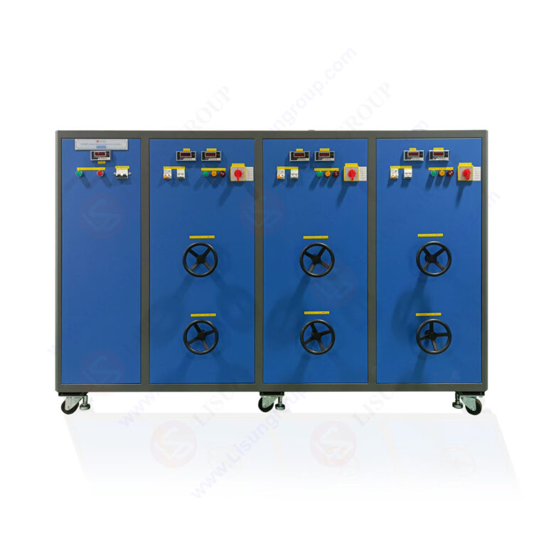
Industrial and commercial switch testing programs typically require currents exceeding 20A, making the DFX-40 or DFX-60 necessary. When testing three-phase switching devices or high-current industrial controls, the DFX-80 delivers the required headroom and 480V line-to-line capability for comprehensive validation.
5.1 LISUN CZKS Series Life Testers
The DFX series integrates seamlessly with LISUN CZKS programmable life testers, creating an automated endurance testing system. The CZKS controller manages test cycles, counts operations, and monitors device-under-test (DUT) status while the DFX cabinet provides the electrical load. This integration enables unattended operation for extended tests requiring thousands of cycles, reducing labor costs and eliminating operator-induced variability.
Communication interfaces including RS-232 and Ethernet allow remote monitoring and data logging, supporting modern laboratory information management systems and audit trail requirements.
5.2 Mechanical Testing Complement
For comprehensive switch testing programs, the LISUN SW-6 bending tester evaluates flexible cord connections while the DFX load cabinet applies rated electrical loads. Combined testing protocols verify both mechanical endurance and electrical performance, providing complete validation aligned with product safety standards.
Temperature monitoring systems can be integrated through dedicated sensor ports, enabling simultaneous thermal evaluation during endurance testing. This multi-parameter approach identifies potential failure modes that single-parameter testing would miss.
6.1 Calibration and Measurement Traceability
The DFX series includes precision current transformers and voltage sensing circuits with accuracy better than ±0.5% of reading. Calibration intervals of 12 months maintain measurement integrity, with documented traceability to national standards through accredited laboratory calibration services.
The measurement uncertainty budget for load testing typically ranges from 1.5% to 2.8% of indicated values, depending on current level and power factor setting. This uncertainty must be considered when determining conformance margins for standard-mandated load parameters.
6.2 Operational Maintenance Requirements
Active cooling systems use replaceable filter elements recommended for inspection at 500-hour service intervals or quarterly, whichever occurs first. Inductor connections should be torque-checked annually to maintain consistent resistance and prevent hot-spot development.
Thermal imaging surveys at six-month intervals identify developing connection degradation before it affects test validity. Replacement components are readily available through LISUN’s global support network, minimizing downtime for critical testing programs.
7.1 Test Setup and Configuration Protocol
Effective DFX series implementation requires systematic configuration following the device-under-test specifications. Start by connecting the load cabinet between the power supply and DUT, then set the current to the required test value using the front-panel control interface.
Adjust power factor incrementally while observing the digital metering display until the target value within tolerance is achieved. Record initial parameters and compare with the standard’s detailed requirements before initiating the endurance test sequence.
7.2 Data Management and Documentation
Modern DFX configurations support automated data capture through software platforms that generate test reports compliant with ISO 17025 documentation requirements. Digital records include timestamps, load parameters, test cycles completed, and any abnormal events detected during testing.
This automated documentation eliminates transcription errors and provides court-admissible evidence for product compliance certifications. Integration with laboratory information management systems further enhances traceability and quality system conformance.
The LISUN DFX series externally ballasted fluorescent lamp test load cabinets represent a comprehensive solution for switch testing compliance laboratories and manufacturers. With current capabilities spanning 20A to 80A, power factor adjustment from 0.3 to 1.0 at 0.01 resolution, and multi-channel configurations, the series addresses diverse testing requirements across international standards including IEC 60669-1, IEC 60884-1, IEC 61058-1, and IEC 60669-2-1.
The precision engineering of inductive and resistive components ensures accurate simulation of real-world ballasted lighting loads, while robust safety systems protect both operators and test devices. Integration capabilities with complementary LISUN equipment create complete automated testing workflows that improve throughput and repeatability.
For testing engineers and quality managers, investment in proper load simulation technology directly correlates with certification success and product reliability in the field.
Q1: What is the difference between resistive and inductive load testing for switches, and why is the inductive component essential?
A: Resistive loads simulate purely resistive circuits like incandescent lighting, while inductive loads replicate the behavior of motors, transformers, and ballasted lighting systems where current lags voltage due to energy storage in magnetic fields. When a switch interrupts an inductive circuit, the stored energy attempts to maintain current flow, causing arcing across opening contacts. This arcing accelerates contact erosion and potentially leads to premature failure or safety hazards. The DFX series independently adjusts resistive and inductive components, enabling testing under worst-case lagging power factor conditions specified by IEC standards. Without inductive test capability, switch designs might pass certification testing yet fail dramatically in real-world installations serving fluorescent lighting circuits.
Q2: How does the DFX-20-3CH increase testing efficiency for third-party laboratories?
A: The three-channel configuration allows simultaneous testing of three separate switches under identical or individually configured load conditions. This parallel testing approach triples throughput compared to single-channel load cabinets while maintaining electrical isolation between channels. Testing laboratories processing multiple certification applications benefit from reduced total test time and better utilization of operator resources. Additionally, the independent channel controls permit side-by-side comparison testing, where a reference product and competing product undergo identical endurance cycles, providing directly comparable performance data. The multi-channel design also supports differential testing at different power factors simultaneously, accelerating design validation programs for manufacturers evaluating alternative switch configurations.
Q3: What calibration procedure is required for maintaining DFX series load cabinets?
A: Annual calibration performed by an accredited laboratory is recommended to maintain measurement accuracy and traceability standards. The calibration procedure verifies current output accuracy across the full range at multiple power factor settings using calibrated reference instruments traceable to national standards. Voltage sensing circuits undergo verification across their operational envelope, and power factor adjustment mechanisms are checked for precision and repeatability. After calibration, the laboratory issues a certificate documenting actual performance versus specified tolerances of ±0.5%. Between annual calibrations, monthly verification using a stable reference load identifies any drift requiring investigation. This systematic approach ensures consistent test validity and supports successful certification audits.
Q4: Can the DFX series load cabinets test switches rated for higher currents than the cabinet’s maximum rating?
A: No, testing at currents exceeding the cabinet’s rated capability risks component damage and invalidates results. Each model has a defined maximum current: 20A for DFX-20 and DFX-20-3CH, 40A for DFX-40, 60A for DFX-60, and 80A for DFX-80. When evaluating switches rated above these limits, select a higher-capacity model or implement alternative load simulation strategies. Transformer-based load banks can step up the applied current while using the load cabinet’s control signals, but this approach requires careful validation of the resulting load characteristics and may not satisfy all standard requirements. For industrial switchgear rated above 80A, specialized high-current test equipment is necessary.
Q5: What safety features protect operators and test devices when using the DFX series?
A: Multiple protection layers ensure safe operation. Thermal monitoring continuously tracks winding temperature and derates output before overtemperature conditions develop. Overcurrent relays trip instantaneously on fault conditions, isolating the DUT and load circuits from the supply. Emergency stop controls provide immediate shutdown capability, and the IP20-rated enclosure prevents accidental contact with live components. Voltage and current monitoring through isolated outputs prevents ground loops that could create shock hazards. The units feature thermal cutoff devices wired in the control circuit, removing power when internal temperature exceeds safe limits. Comprehensive labeling and documentation support safe operating procedures, and the rapid connection terminals accept standard fork or ring terminals with adequate diameter ratings.