




Glow Wire Test for Plastics: A Comprehensive Guide to IEC 60695-2-11 Flammability Testing
Introduction: The Necessity of Standardized Flammability Assessment in Polymer Materials
The proliferation of polymeric materials in modern electrical and electronic assemblies has introduced critical challenges regarding fire safety. Plastics, prized for their dielectric properties, mechanical flexibility, and cost-effectiveness, are inherently combustible under fault conditions such as short circuits or component overloads. The IEC 60695-2-11 standard, governing the Glow-Wire Flammability Test (GWF), was established to simulate the thermal stress exerted by an overheated component or conductor. This test method, distinct from other flammability protocols like UL 94 or the Needle-Flame Test, specifically evaluates the capacity of a material or finished product to resist ignition from a red-hot element and, critically, to self-extinguish. This article delineates the theoretical underpinnings, procedural mechanics, and industrial relevance of the GWF, while examining the role of precision instrumentation—such as the LISUN ZRS-3H Glow-wire Test Apparatus—in achieving reproducible and compliant results.
Substantiating the Standard: IEC 60695-2-11 and Its Role in Global Compliance
IEC 60695-2-11 is not an isolated document but forms part of the extensive IEC 60695 series covering fire hazard testing. The standard specifies the detailed method for assessing the flammability of solid insulating materials and products using a heated glow-wire. The core objective is to determine the Glow-Wire Flammability Index (GWFI) and, where applicable, the Glow-Wire Ignition Temperature (GWIT). Unlike tests that rely on an open flame, the GWF simulates the effect of an electrically overstressed resistor or a loose connection, where temperatures can reach 960°C. Compliance is mandated by numerous downstream standards, including IEC 60335-1 for household appliances and IEC 60950-1 for information technology equipment. The test protocol dictates that the glow-wire tip, typically a nickel/chromium (Ni/Cr) alloy wire with a diameter of 4.0 mm, is heated to a prescribed temperature—commonly 550°C, 650°C, 750°C, or 850°C—and applied to the test specimen with a force of 1.0 N for 30 seconds. The critical outcome parameters are whether ignition occurs, the duration of any resulting flame, and whether burning droplets fall onto a specified layer of tissue paper, which would indicate potential propagation of fire to adjacent surfaces.
Deconstructing the Glow-Wire Test Apparatus: Operational Principles and Critical Parameters
The implementation of IEC 60695-2-11 necessitates specialized equipment that can precisely control, monitor, and replicate a highly specific thermal stress scenario. A standard apparatus comprises several interdependent subsystems: the glow-wire probe, a specimen carriage, a temperature measurement system, a timing mechanism, and a draft-free enclosure. The glow-wire itself is formed into a loop with a defined radius and is electrically heated. The temperature of the wire is measured by a fine-wire thermocouple (type K, 0.5 mm diameter) welded to the tip. The critical challenge lies in thermal inertia; the wire must reach the target set-point and maintain it within a narrow tolerance (±5 K) during the 30-second application period. The force application mechanism, often a linear guide with a counterweight, must exert precisely 1.0 N upon contact. Any deviation in force influences the contact area and, consequently, the heat transfer efficiency to the specimen. Furthermore, the system must log the ignition time (ti) and the afterflame time (te). The enclosure must provide standard ambient conditions (25 ± 5°C, relative humidity 45–75%) without induced draft, as airflow can artificially alter combustion behavior.
LISUN ZRS-3H Glow-wire Test Apparatus: Instrumentation for High-Fidelity Standard Conformance
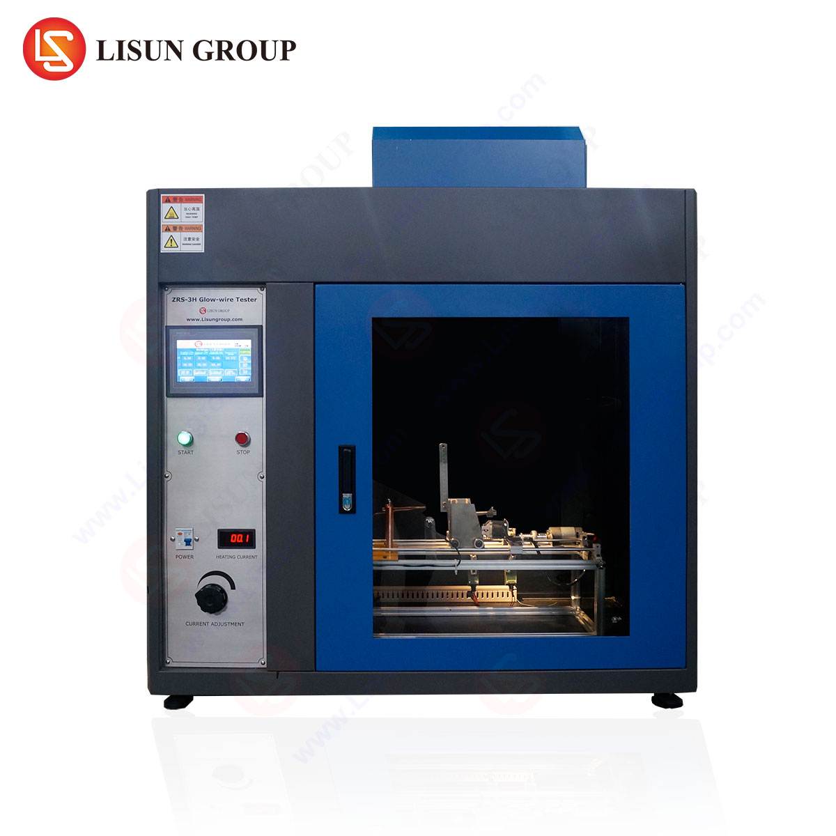
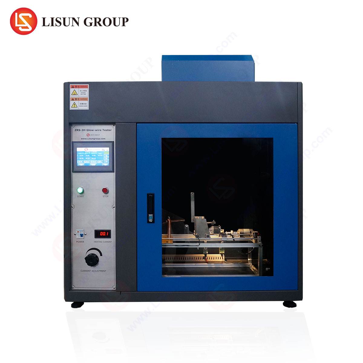
When selecting instrumentation for mandatory pre-compliance and certification testing, the repeatability of thermal delivery is paramount. The LISUN ZRS-3H Glow-wire Test Apparatus is engineered to address the technical demands of IEC 60695-2-11, IEC 60695-2-10, and associated standards like UL 746A. The ZRS-3H features a high-precision microcontroller-based temperature control loop that manages the glow-wire heater current. Its internal resistance-temperature coefficient compensation algorithm minimizes overshoot at critical set-points, which is a common flaw in less sophisticated systems that can degrade wire integrity and invalidate test sequences.
The mechanical design incorporates a stepper-motor-driven traversing system for the specimen carriage, ensuring consistent and reproducible application of the 1.0 N contact force. The apparatus includes a transparent polycarbonate safety shield, which is interlocked to prevent operator exposure during testing. A critical differentiator of the ZRS-3H is its integrated timing system capable of resolving ignition events to 0.1 seconds, with dedicated channels for measuring both application time and afterflame time. The unit also incorporates a calibrated tissue paper positioning tray, precisely located 200 ± 5 mm below the point of contact, as required by the standard for assessing burning droplet propagation risk.
Table 1: Technical Specifications of the LISUN ZRS-3H Glow-wire Test Apparatus
| Parameter | Specification |
|---|---|
| Glow-wire Material | Nickel/Chromium (Ni/Cr) 80/20, Ø 4.0 mm |
| Temperature Range | Ambient to 1050°C |
| Temperature Accuracy | ±5°C (100 – 1000°C) |
| Application Force | 1.0 N ± 0.1 N |
| Contact Duration | 30 s ± 1 s (adjustable) |
| Flame Measurement | Resolution 0.1 s |
| Specimen Holder | Adjustable, for planar and small parts |
| Power Supply | 220V/50Hz (or 110V/60Hz) |
| Interior Volume | >0.5 m³ (draft-free enclosure) |
| Safety Features | Interlock switch, emergency stop, over-temp protection |
Application Domain Analysis: The GWF in Electrical and Electronic Equipment
The GWF is most heavily applied within the Electrical and Electronic Equipment (EEE) sector. For components such as switches, sockets, and connectors used in household appliances and industrial control systems, the GWF test at 750°C is a frequent requirement under IEC 60335-1. Consider a polyamide (PA6) connector used in a washing machine controller; without a glow-wire rating, an arcing failure in the relay could cause the connector to ignite. The ZRS-3H is used to qualify the material’s flame retardant additive package, verifying that the connector does not sustain a flame for more than 2 seconds after wire removal. In telecommunications equipment, where densely populated printed circuit boards (PCBs) contain gold fingers and edge connectors, the test evaluates both the substrate material (e.g., FR-4) and the housing plastic (e.g., PC/ABS). A failure to meet the GWFI standard often results in the requirement for significantly thicker plastic walls or the use of more expensive, high-temperature thermoplastics like PEEK.
Extended Sector Applications: Automotive, Aerospace, and Medical Devices
The automotive electronics industry has adopted the GWF test, often with more stringent criteria that align with ISO 6722 or LV 112. Components inside the passenger cabin, such as fuse boxes, electronic control units (ECUs), and lighting bezels, are subjected to the GWF. The primary concern in this environment is the liberation of toxic fumes versus the spread of flame, but the glow-wire test specifically addresses the latter. For example, an ABS housing for an infotainment module must demonstrate non-ignition at 700°C. The LISUN ZRS-3H allows automotive test labs to run the necessary preconditioning (e.g., 168 hours at 85°C) before performing the test, a step that can be programmed directly into the unit’s controller.
In aerospace and aviation components, the GWF is often a supplementary test to the vertical burn test (FAR 25.853). While aluminum alloys are the primary structural materials, plastics are used extensively in galley inserts, ducting, and interior trim. The glow-wire test here validates the plastic’s resistance to ignition from a failed heating element—a scenario highly relevant to in-flight galleys. Medical devices, particularly diagnostic imaging equipment and patient monitoring systems, utilize high-performance engineering plastics. The GWF test on a housing for a defibrillator ensures that a fault in the internal power supply does not cause the casing to become a fuel source. For such applications, the ZRS-3H provides the data sheets necessary for regulatory filings with bodies like the FDA or TÜV.
Comparative Analysis: The GWF versus Alternative Flammability Test Protocols
It is critical to differentiate the GWF from other common flammability tests to understand its unique contribution. The UL 94 HB and V-0/V-1 tests use a methane burner and a conditioned specimen, measuring the ability of the material to resist ignition from a diffusion flame. The GWF, conversely, uses a conductive, solid heating source. This distinction is crucial: a material can achieve a V-0 rating but fail the GWF at 750°C because the thermal energy penetration is deeper and the pyrolysis occurs in a different spatial pattern. The GWF correlates more directly with real-world electrical fault scenarios.
The Needle-Flame Test (IEC 60695-11-5) simulates a small fire from a fault source, but its flame is directed at the specimen. The GWF applies a conductive heat source, which is more relevant for abutting components. For Cable and Wiring Systems, the GWF is less common than the vertical flame test for wires (IEC 60332-1-2), but it is essential for evaluating the cable tie or grommet that secures the wiring bundle. The ZRS-3H can be configured with a specialized specimen holder for small parts and wire grommets, ensuring that the contact point aligns precisely with the critical surface. For Lighting Fixtures (IEC 60598-1), the GWF at 650°C is a baseline requirement for insulating materials, preventing a heated junction box from igniting the plastic lens.
Procedural Execution and Critical Observational Metrics
Standard compliance on the ZRS-3H requires a disciplined procedural approach. First, the operator verifies the calibration of the thermocouple against a reference source. The specimen, typically 60mm x 60mm x thickness, is conditioned at 23°C/50% RH for 48 hours. The test is conducted in three runs (or five for classification). The machine aligns the glow-wire loop perpendicular to the specimen’s surface. Upon contact, the operator monitors three distinct phases:
- Ignition Delay: The time from contact to sustained flaming combustion.
- Flame Propagation: The vertical extent of the flame and whether it contacts the indicator paper.
- Self-Extinguishment: The time from glow-wire removal to flame extinction.
The ZRS-3H automatically records these events, but the operator must document the presence of molten drips, the color of the smoke, and any evidence of charring beyond the contact area. A failure occurs if the afterflame time exceeds 30 seconds or if the tissue paper ignites. The unit’s software allows direct data export to CSV for inclusion in certification reports. It is also important to perform an aging test on the glow-wire itself; repeated heating to 960°C can cause the Ni/Cr alloy to oxidize and embrittle, altering its thermal emissivity. The ZRS-3H includes a diagnostic routine that monitors the resistive stability of the wire, alerting the operator to replacement intervals.
Material Chemistry and Thermal Degradation Dynamics
The GWF probes the thermochemical resilience of polymers. During the test, the specimen surface reaches temperatures exceeding the polymer’s degradation temperature, typically between 300°C and 500°C for most commodity plastics. Chain scission occurs, producing volatile oligomers and monomers. The material’s ability to undergo endothermic decomposition (e.g., via release of water from metal hydroxides in flame retardants) or to form a protective char layer is critical. For instance, polycarbonate (PC) naturally forms an insulating char, which explains its relatively good GWF performance even without additives. In contrast, polypropylene (PP) often requires brominated flame retardants or intumescent systems to meet a 750°C GWF rating. The LISUN ZRS-3H, with its consistent heating profile, allows material scientists to accurately differentiate between these mechanisms without the variable input of an open flame. The use of a 4.0 mm wire diameter ensures a specific contact area (approximately 12.5 mm²), and any deviation in wire shape due to manufacturing tolerance can skew results by 5–10°C equivalent thermal load.
Frequently Asked Questions (FAQ)
Q1: Can the LISUN ZRS-3H be used to test both solid materials and finished products?
Yes. The ZRS-3H is designed to accept a range of specimen holders. For flat sheet materials, standard 60mm x 60mm plaques are used. For finished products, such as a switch housing or a terminal block, the unit allows clamping of the entire component, provided the test point can be positioned perpendicular to the glow-wire tip. The operator must ensure that the contact point is on a surface with minimal curvature to maintain consistent thermal coupling.
Q2: What is the typical calibration frequency for the ZRS-3H to maintain compliance with IEC 60695-2-11?
Routine calibration of the temperature measurement system (thermocouple and controller) is recommended every 12 months or after every 500 test cycles, whichever comes first. The force application mechanism should be verified every 3 months using a calibrated load cell. The ZRS-3H includes a self-diagnostics menu that compares internal resistance measurements to stored calibration curves, but external calibration traceable to a national standard (e.g., NIST) is mandatory for laboratory accreditation (ISO 17025).
Q3: How does the ZRS-3H handle the problem of molten plastic adhesion to the glow-wire?
This is a known issue in GWF testing. Molten residue on the glow-wire alters its thermal mass and emissivity, invalidating subsequent tests. The ZRS-3H incorporates a special high-temperature alloy wire with a low coefficient of adhesion for most thermoplastics. Additionally, the operator can perform a “burn-off” cycle by heating the wire to 960°C for 30 seconds between tests. If residue persists, the wire must be replaced. The instrument logs the number of contact cycles, providing a clear maintenance protocol.
Q4: Is the GWF test suitable for determining the flame spread index of a material?
No, the test does not quantify flame spread. The primary outputs are ignition resistance (maximum temperature without ignition) and afterflame duration. For flame spread classification (e.g., Class A, B, C), tests such as the Steiner Tunnel Test (ASTM E84) or the UL 723 are required. The GWF establishes a pass/fail criterion for fire initiation from a hot element, not for the propagation of existing fire along a surface.
Conclusion
The glow wire test under IEC 60695-2-11 provides a definitive, quantitative assessment of a material’s response to a high-temperature ignition source, simulating realistic electrical fault conditions. The rigorous application of this standard is non-negotiable for manufacturers in the electrical, automotive, and appliance sectors. Instruments like the LISUN ZRS-3H Glow-wire Test Apparatus afford the precision, repeatability, and data management necessary to navigate the complexities of global compliance. By integrating advanced temperature control with robust mechanical execution, the ZRS-3H serves as a critical tool for materials qualification, quality assurance, and the ultimate mitigation of fire risk in a wide spectrum of industries. Its adoption facilitates the development of safer products, from the simple socket to the advanced aerospace component.