


Title: A Rigorous Protocol for Assessing Fire Hazard Risk in Electrotechnical Products via the Glow-Wire Test Method
Author: [Attribution to a Technical Standards Body or Independent Laboratory]
Document Type: Technical Procedure / Industry Whitepaper
Subject: Implementation of the LISUN ZRS-3H Glow-wire Test Apparatus for IEC 60695-2-11 Compliance
1. Establishing the Context for Glow-Wire Testing in Contemporary Product Safety
The proliferation of low-voltage, high-density electrical assemblies across sectors—from telecommunications infrastructure to medical monitoring devices—has necessitated a paradigm shift in fire hazard assessment methodologies. The fundamental risk is not always an open flame but rather the incipient thermal event: an overheated conductor, a loose connection in a terminal block, or a resistive fault within a printed circuit board (PCB). Such anomalies can generate surface temperatures sufficient to initiate secondary combustion in adjacent polymeric materials, such as housings, insulators, or wire jacketing.
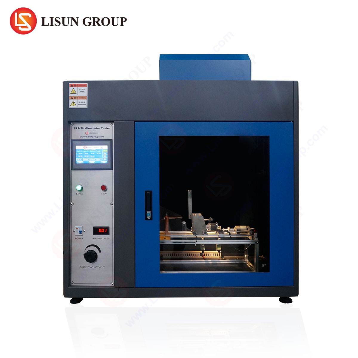
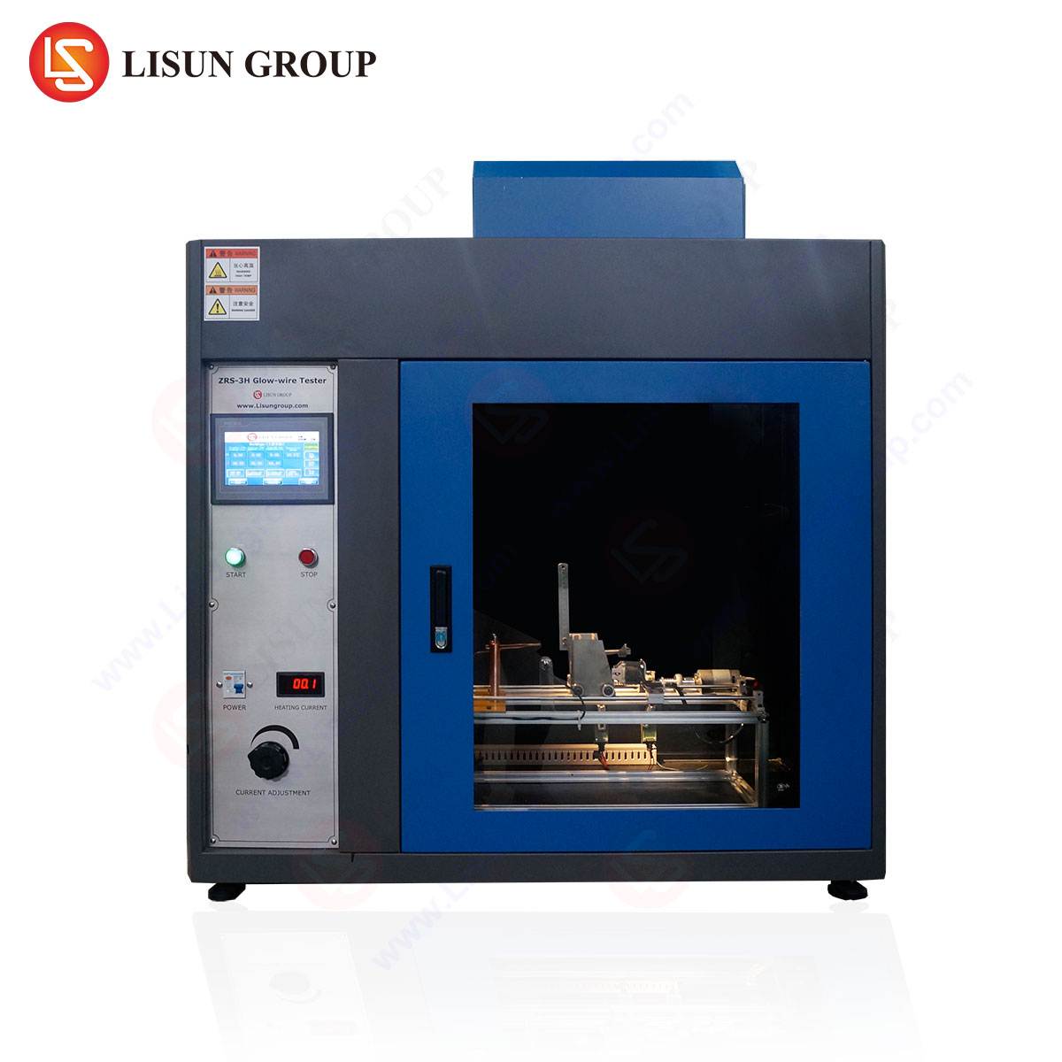
The glow-wire test, as codified in the IEC 60695-2-11 series, simulates this specific stressor. It evaluates the ability of a material or finished product to resist ignition and inhibit flame propagation when subjected to a calibrated, electrically heated element. The apparatus used to conduct this evaluation must possess high precision in temperature control, force application, and timing. The LISUN ZRS-3H Glow-wire Test Apparatus represents a specialized implementation of this standard, offering micro-processor governed control loops and a modular fixture design suited for a diverse range of sample geometries. This procedure delineates the operational protocol for utilizing the ZRS-3H to achieve reproducible, diagnostically meaningful results.
2. Operational Principles of the LISUN ZRS-3H and Sensor Calibration
The ZRS-3H operates on a closed-loop thermal feedback system. The core component is a nickel/chromium (Ni/Cr) resistance wire loop, shaped into a standardized tip geometry. The temperature of this tip is measured by a sheathed thermocouple (Type K, 0.5 mm diameter) embedded within the glow-wire coil, positioned directly behind the exposed loop. The apparatus uses a PID (Proportional-Integral-Derivative) controller to modulate current through the Ni/Cr wire, maintaining the set-point temperature within a tolerance of ±5°C up to a maximum of 1000°C, though standard testing typically occurs at 550°C, 650°C, 750°C, or 850°C.
Crucial Calibration Protocol:
Before any test sequence, the user must verify the thermal accuracy using a certified reference pyrometer or a secondary calibrated thermocouple. The ZRS-3H incorporates a self-diagnostic routine for checking the cold resistance of the glow-wire loop, which can indicate oxidation or mechanical wear of the element. Force calibration is equally critical; the apparatus applies the glow-wire to the specimen with a standard force of 1 Newton (N) ± 0.2 N. The LISUN ZRS-3H utilizes a counterweight and lever system, verified by a precision load cell integrated into the sample carriage. Failure to calibrate the force mechanism results in inconsistent surface contact area, producing high variability in ignition time (ti) and flame extinction time (te).
Table 1: Standard Calibration Parameters for LISUN ZRS-3H
| Parameter | Requirement | ZRS-3H Verification Method | Acceptance Criteria |
|---|---|---|---|
| Temperature Accuracy | ±5°C (300°C – 1000°C) | External Pyrometer / Calibrated Type K TC | Deviation ≤ 5°C |
| Contact Force | 1.0 N ± 0.2 N | Integrated Load Cell (NIST traceable) | 0.8 N to 1.2 N |
| Glow-wire Geometry | Loop Diameter 4.0 mm | Optical Comparator / Digital Caliper | ± 0.1 mm |
| Thermocouple Response | < 500ms to 63% of ΔT | Internal Diagnostic Pulse Test | Pass/Fail Indication |
3. Specimen Preparation and Conditioning for Diverse Industry Substrates
The repeatability of the glow-wire test is highly sensitive to sample preparation. The ZRS-3H accommodates specimens of varying thicknesses, from thin films (e.g., wire insulation in aerospace connectors) to thick molded sections (e.g., enclosures for industrial control systems). The procedure mandates that the specimen be a representative cross-section of the final product, typically no smaller than 15 mm x 15 mm and no thicker than 20 mm, although the apparatus’s adjustable clamping mechanism allows for non-standard geometries prevalent in lighting fixtures and automotive electronic control units (ECUs).
Conditioning Standards:
Specimens must be conditioned at 23°C ± 2°C and 50% ± 5% relative humidity for a minimum of 24 hours prior to testing. For medical device components or consumer electronics casings that undergo sterilization or exposure to cleaning agents, a secondary conditioning at 70°C for 168 hours (dry heat aging) is often specified to simulate long-term thermal degradation of the polymer. The ZRS-3H’s sample holder is designed with interchangeable base plates to accommodate the specific mounting requirements of different industries—for instance, a specialized clamp for testing cable tie materials in aerospace applications or a recessed holder for PCB laminate sections used in office equipment.
4. Execution of the Glow-Wire Test: A Stepwise Operational Sequence
The following sequence is specific to the LISUN ZRS-3H Glow-wire Test Apparatus to ensure compliance with IEC 60695-2-11.
Step 1: System Initiation and Environmental Isolation.
Power on the ZRS-3H. Allow the PID controller to stabilize for 10 minutes. Ensure that the test chamber is placed within a draft-free environment, as air currents significantly alter pyrolysis and flame spread. The chamber’s internal exhaust fan should be turned off for the duration of the test to avoid artificially influencing the flame.
Step 2: Parameter Input.
Using the integrated touch-screen interface, input the target temperature (e.g., 750°C for a household appliance housing). Set the application duration to the standard 30 seconds ± 1 second. Configure the data logging parameters for recording time to ignition (ti), flame duration (ta), and peak temperature during the event.
Step 3: Specimen Mounting.
Secure the conditioned specimen in the carriage. For lighting fixture components, ensure the surface to be tested is oriented perpendicular to the axis of the glow-wire. For wire and cable samples (e.g., cable and wiring systems), the sample must be wound around a mandrel or secured in a U-shape to ensure consistent contact with the wire tip. The ZRS-3H’s pneumatic clamping system minimizes human-induced variability in mounting torque.
Step 4: Application of the Thermal Stressor.
Activate the test sequence via the start button. The ZRS-3H automatically initiates the movement of the carriage, bringing the specimen into contact with the pre-heated glow-wire tip under the calibrated 1N force. The timing mechanism begins upon physical contact, detected by a micro-switch. The operator must visually monitor the sample for the first 5 seconds, as the most critical exothermic reactions occur during this window.
Step 5: Assessment of Ignition and Flame Propagation.
Two primary criteria define the test outcome: (a) Did the specimen ignite? (b) If ignition occurs, does the resulting flame self-extinguish within 30 seconds (te ≤ 30s)? The ZRS-3H automatically measures te using a photodiode sensor located within the chamber ceiling. This sensor detects the luminous intensity of the flame and stops the timer upon extinction. The operator must also note the presence of any incandescent particles (glowing droplets) that fall from the specimen, which are a significant secondary fire risk.
Step 6: Removal and Post-Test Analysis.
After the glow-wire retracts and the flame has extinguished, the ZRS-3H provides a digital report of ti, te, and maximum flame height. The sample is removed for inspection. For automotive electronics applications (e.g., sensor housings near high-temperature engine components), a measurement of the char length and damaged area using an optical micrometer is required to pass OEM specifications.
5. Interpretation of Results and Determining Failure Modes
The raw data from the ZRS-3H—specifically the time to ignition (ti) and flame time (te)—must be contextualized against the product’s end-use environment. A test result is classified as a “PASS” only if:
- The specimen does not ignite, OR
- The flame self-extinguishes (te) within 30 seconds, AND
- Any falling droplets do not ignite a layer of tissue paper placed 200 mm below the specimen (simulating a flammable substrate).
Analysis of Non-Ignition:
A high ti value (close to or exceeding the 30-second application period) suggests a material with high thermal inertia or a char-forming mechanism, common in halogen-free flame retardants used in telecommunications equipment. However, a material that does not ignite under a 550°C glow-wire may still fail at 650°C. The LISUN ZRS-3H permits rapid temperature stepping for material screening.
Analysis of Droplet Ignition:
In industrial control systems and office equipment, gravity-assisted dripping of molten polymer can carry the heat source to lower areas of the assembly. The ZRS-3H’s integrated tissue support tray is precisely positioned per the standard. Any ignition of the tissue is an automatic failure, regardless of the te value. This is a critical differentiator for high-wall creepage materials used in electrical components like switches and sockets.
Table 2: Correlation of ZRS-3H Results with Industry Standards
| Industry Application | Typical Test Temperature | Critical Failure Criterion | ZRS-3H Measurement Capability |
|---|---|---|---|
| Household Appliances | 750°C | te > 2s | High-speed photodiode (1ms resolution) |
| Lighting Fixtures | 650°C | Droplet ignition of tissue | Visual confirmation + timed log |
| Automotive Electronics | 850°C | Ignition within 5s | Real-time current/voltage monitor |
| Medical Devices | 550°C | te > 30s | Automatic test termination |
6. Maintenance Regimen for the LISUN ZRS-3H to Ensure Data Integrity
The validity of the glow-wire test is contingent on the physical condition of the thermal source. The LISUN ZRS-3H requires a rigorous maintenance schedule to prevent drift.
Glow-Wire Element Replacement:
The Ni/Cr wire loop degrades through oxidation and carburization during each test cycle. The apparatus includes a cycle counter. After 50 tests (or immediately after a test where erratic temperature control is observed), the glow-wire element must be replaced. The ZRS-3H’s quick-release terminal block simplifies this exchange, reducing downtime. A new element must be thermally cycled (heated to 700°C for 60 seconds, then cooled) three times before use to stabilize its crystalline structure.
Thermocouple Integrity:
The embedded Type K thermocouple is a wear item. Exposure to molten polymer residue can cause bridging or mechanical damage. The LISUN ZRS-3H provides a specific diagnostic function to measure the thermocouple’s cold-junction compensation accuracy. Any reading that deviates by more than 2°C from the ambient temperature probe requires thermocouple replacement.
Mechanical Alignment:
Verify the perpendicularity of the glow-wire axis to the sample plane after every 100 tests. Misalignment, often caused by vibration during the carriage retraction sequence, alters the contact angle and the effective force distribution. The ZRS-3H includes mechanical stops that require adjustment using a spirit level and a dedicated alignment jig supplied with the unit.
7. Competitive Advantages of the ZRS-3H in High-Throughput Laboratories
In industrial settings—particularly those servicing multiple sectors such as cable and wiring systems for aerospace alongside consumer electronics testing—throughput without sacrificing precision is paramount. The LISUN ZRS-3H offers several distinct operational advantages over legacy apparatus designs.
Integrated Data Management:
The ZRS-3H features an onboard SQLite database for storing test parameters and results. This is critical for audit trails required by ISO 17025 accredited laboratories. The ability to export CSV data directly to a USB device eliminates manual transcription errors.
Adaptable Fixturing:
Unlike apparatus with fixed sample holders, the ZRS-3H’s modular base allows for rapid switching between a standard flat-plate clamp and a specialized fixture for cylindrical specimens (e.g., for testing cable ties in telecommunications equipment or wire harnesses in automotive applications). This reduces changeover time from approximately 15 minutes to under 90 seconds.
Safety Interlocks:
High-temperature testing presents an operator risk. The ZRS-3H is equipped with a dual-layer interlock system: a micro-switch on the chamber door and a thermal cutoff on the exhaust manifold. The apparatus will not initiate a test cycle unless the door is fully sealed, preventing exposure to potential polymer fumes or flash flames.
8. Specialized Applications: Testing Beyond Standard Flat Sheets
The standard IEC glow-wire test is defined for flat specimens; however, many final products contain complex features such as ribs, bosses, and edges. The ZRS-3H can be configured for edge testing as a deviation from the standard planar testing. This is particularly relevant for medical device housings and aerospace components where the material thickness at the edge is the thinnest and most vulnerable to thermal breach.
Protocol for Edge Testing:
The sample is rotated 90 degrees relative to the standard holding fixture. The glow-wire tip is applied to the machined edge. The standard specifies a temperature reduction of 50°C for edge compared to planar testing due to the higher stress concentration. The ZRS-3H’s software allows the user to pre-program this variable as a “Test Profile” for repeatability. This capability is often lacking in lower-cost apparatus and is a significant differentiator for R&D departments screening new polymer blends for switches and sockets.
9. Calibration Frequency and Accreditation Requirements
To maintain the validity of the data produced by the LISUN ZRS-3H, a rigorous calibration schedule must be adhered to. The following intervals are recommended:
- Daily: Verification of ambient temperature and visual inspection of the glow-wire loop for oxidation.
- Weekly: Verification of contact force using an external force gauge (NIST traceable).
- Monthly: Full thermal calibration using a certified blackbody or reference pyrometer across three temperature points (550, 750, 950°C).
- Annually: Full instrument recalibration by the manufacturer (LISUN) or an accredited metrology lab, including replacement of all critical consumables.
Records from the ZRS-3H’s internal logging system must be archived. These records serve as evidence for product liability defense, particularly in the electrical and electronic equipment sector, where traceability of material flammability characteristics is increasingly subject to regulatory scrutiny.
10. Conclusion of the Operational Protocol
The LISUN ZRS-3H Glow-wire Test Apparatus serves as a critical instrument for mitigating fire risk in a wide spectrum of electrotechnical products. Its adherence to the IEC 60695-2-11 series, combined with its modular design and integrated data acquisition, provides laboratories with the necessary tools to generate reliable, defensible data. Strict adherence to the calibration and operational procedures outlined herein is essential for obtaining consistent results across different sample types—from the thin wire insulation in cable and wiring systems to the thick-walled enclosures of industrial control systems. Failure to maintain this discipline introduces noise into the data, undermining the very purpose of the test: to accurately characterize the material’s response to an abnormal thermal stress.
Frequently Asked Questions (FAQ)
Q1: Can the LISUN ZRS-3H test samples that are not flat, such as curved panels from household appliances?
Yes. The ZRS-3H’s clamping system has adjustable anvils and a limited degree of rotational freedom. However, the standard requires that the glow-wire tip makes perpendicular contact with the material surface. For curved specimens, a section may need to be cut and mounted to approximate a flat plane, provided this does not alter the material’s thermal properties. The ZRS-3H’s flexibility in clamp positioning is superior to fixed-bed designs for this task.
Q2: What is the most common cause of false positive (Pass) results in glow-wire testing using the ZRS-3H?
The most common cause is incorrect force calibration. If the applied force is below the 0.8 N threshold, the thermal contact resistance increases dramatically. This means the material surface heats slower than the glow-wire set point, potentially preventing ignition. The ZRS-3H’s integrated load cell, if verified weekly, eliminates this failure mode. Also, ensure the polymer is not heavily plasticized, as these can melt away from the tip prematurely.
Q3: How does the ZRS-3H handle the disposal of molten polymer droplets that burn the test chamber floor?
The ZRS-3H chamber floor is made of a high-temperature resistant ceramic fiber board. Molten droplets that do not ignite the tissue paper are allowed to cool and solidify on this board. The board is a replaceable consumable part. The apparatus includes a side-access port for cleaning the floor board without disassembling the chamber, which is a significant ease-of-maintenance advantage.
Q4: Is the ZRS-3H suitable for testing materials used in high-altitude aircraft where air density is lower?
The standard glow-wire test is conducted at standard atmospheric pressure (approx. 101.3 kPa). For aerospace applications requiring hypobaric testing, the ZRS-3H is not directly suitable unless it is modified with a pressure vessel interface. The standard instrument is optimized for terrestrial applications. However, the data from ground-level testing is often used as a baseline for material qualification in higher-altitude environments.