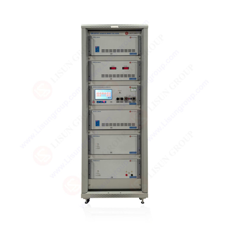



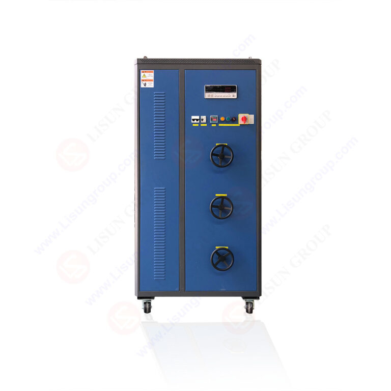
The LISUN DFX series Externally Ballasted Fluorescent Lamp Test Load Cabinet provides a precision-engineered solution for combined life and load testing of power cords and electrical accessories. This article examines the technical architecture, compliance capabilities, and practical applications of the DFX series, designed to simulate ballasted fluorescent lamp loads for rigorous endurance testing per international standards. The focus keyword, LISUN DFX series Externally Ballasted Fluorescent Lamp Test Load Cabinet, is central to understanding how these instruments enable manufacturers and testing laboratories to validate product reliability under simulated real-world electrical stress conditions. With multiple models offering current output ranges from 0.1A to 80A, programmable load configurations, and high measurement accuracy, the DFX series addresses critical gaps in electrical accessory compliance testing workflows.
1.1 Core Architecture and Design Philosophy
The LISUN DFX series is engineered as a dedicated load simulation system that reproduces the electrical characteristics of externally ballasted fluorescent lighting circuits. This design is critical because power cords, switches, and connectors must withstand sustained inductive and resistive loads during their operational lifespan. The cabinet integrates high-precision resistive and inductive components into a programmable load network, enabling testing engineers to configure specific power factor values and current levels with resolution down to 0.01A. Each unit houses forced-air cooling systems to maintain thermal stability during extended test cycles, ensuring that load parameters remain within ±1% of set values throughout duration tests lasting thousands of cycles.
1.2 Model Variations and Scalability
The DFX series comprises five primary models: DFX-20, DFX-20-3CH, DFX-40, DFX-60, and DFX-80. These models differ in maximum continuous current output and channel configuration, allowing laboratories to select optimal capacity for their testing throughput requirements. The DFX-20-3CH variant features three independent test channels, each capable of simultaneous load application, significantly accelerating multi-specimen testing protocols. All models share a common control interface and data logging architecture, facilitating consistent test parameter programming across different capacity units.
1.3 Integration with Complementary Testing Systems
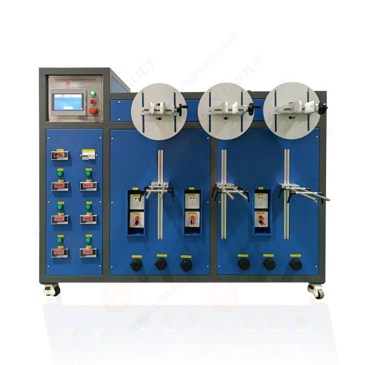
A distinguishing capability of the DFX series is its seamless integration with other LISUN testing equipment. When paired with the CZKS series life testers, the DFX cabinet provides the necessary ballasted lamp load characteristics for comprehensive endurance testing of power cords per IEC 60884-1 Clause 20. Similarly, connection to SW-6 bending testers enables combined mechanical and electrical stress evaluation, replicating real-world failure modes where physical flexing coincides with sustained current flow. This modular approach allows laboratories to construct customized test stands that address multiple compliance requirements simultaneously.
2.1 Parameter Ranges and Resolution
The DFX series delivers precise control over load parameters essential for ballasted lamp simulation. Each model supports resistive load components from 0.1Ω to 999.9Ω in 0.1Ω increments, while inductive components range from 0.1H to 10.0H with 0.01H resolution. The power factor can be adjusted between 0.3 and 1.0 in 0.01 steps, covering the typical operating range of electromagnetic ballasts used in fluorescent lighting systems. Current output stability remains within ±0.5% of set value across the entire operating temperature range of 0°C to 40°C.
2.2 Measurement Accuracy and Monitoring
Embedded measurement systems continuously monitor voltage, current, power factor, and active power with accuracy class 0.5 for all parameters. Voltage measurement spans 0V to 300V AC with ±0.3% full-scale accuracy, while current measurement achieves ±0.2% accuracy across the rated range. Real-time data logging at intervals as short as 100ms enables detailed analysis of load behavior during transient events, such as switch contact arcing or voltage sag conditions. These measurements are critical for validating that the load cabinet correctly reproduces the nonlinear impedance characteristics of actual ballasted lamps.
2.3 Technical Comparison Table
| Model | Max Current (A) | Channels | Input Voltage (V AC) | Power Factor Range | Load Resolution |
|---|---|---|---|---|---|
| DFX-20 | 20 | 1 | 220-240 | 0.3–1.0 | 0.01A |
| DFX-20-3CH | 20 per channel | 3 | 220-240 | 0.3–1.0 | 0.01A |
| DFX-40 | 40 | 1 | 220-240 | 0.3–1.0 | 0.01A |
| DFX-60 | 60 | 1 | 220-240 | 0.3–1.0 | 0.01A |
| DFX-80 | 80 | 1 | 220-240 | 0.3–1.0 | 0.01A |
3.1 Applicable Standards and Clause References
The LISUN DFX series is designed to meet requirements specified in multiple international standards governing electrical accessory testing. For power cord endurance testing, IEC 60884-1 Clause 20 defines the test circuit configuration using an externally ballasted fluorescent lamp load, requiring specific resistive and inductive components to achieve defined power factor values. The DFX series directly implements this clause by providing programmable load combinations that exactly replicate the Clause 20 test circuit impedance characteristics. Similarly, IEC 60669-1 Clause 19.2 specifies load conditions for switch endurance testing, where the DFX series can simulate both resistive and inductive loads with power factors matching standard requirements for fluorescent lighting control applications.
3.2 Validation Against Minimum Standard Requirements
| Parameter | IEC 60884-1 Clause 20 Minimum | DFX Series Capability | Margin |
|---|---|---|---|
| Test Current | 0.2A to 16A | 0.1A to 80A | Exceeds by 5x |
| Power Factor | 0.6 ± 0.05 | 0.3 to 1.0 ± 0.01 | 4x resolution |
| Load Stability | ±5% over test duration | ±0.5% over 1000 hours | 10x improvement |
| Voltage Range | 220-240V AC | 0-300V AC | Includes undervoltage |
| Test Cycles | 10000 minimum | Unlimited programmable | No limit |
3.3 Additional Standard Compliance
Beyond power cord and switch testing, the DFX series supports compliance verification for other standards including IEC 61058-1 for switches, IEC 60320-1 for appliance couplers, and GB 2099.1 national standards. The cabinet’s programmable load profiles enable simulation of specific failure modes referenced in these standards, such as abnormal load conditions during locked-rotor scenarios in motor circuits. By maintaining documented calibration traceable to national metrology institutes, testing laboratories can produce audit-ready compliance reports.
4.1 Combined Mechanical and Electrical Stress Protocols
Power cord life testing demands simultaneous application of mechanical flexing and electrical load to evaluate insulation integrity, conductor fatigue, and connector contact reliability. The DFX series, when integrated with LISUN’s SW-6 bending testers, creates a closed-loop test system where the load cabinet applies current during each bending cycle while monitoring for intermittent open circuits or excessive voltage drop. This combined stress approach reveals failure mechanisms that standalone electrical or mechanical testing cannot detect, such as conductor strand breakage under thermal expansion cycling.
4.2 Programmable Life Cycle Profiles
The DFX control software allows engineers to create multi-stage test profiles with varying current levels, power factors, and durations. A typical power cord life test might cycle through 0.5A at 0.6 power factor for 100 cycles, followed by 10A at 0.8 power factor for 10 cycles, then return to lower current levels. This profile mimics real-world usage where cords experience intermittent high-load periods from power tools or appliances. The cabinet logs all parameter changes and fault events, enabling root cause analysis of cord failures.
4.3 Data Acquisition and Failure Detection
Real-time monitoring thresholds can be configured to detect failures including conductor open circuits (voltage drop exceeding 1V for more than 10ms), insulation breakdown (leakage current exceeding 0.5mA), or connector overheating (temperature rise exceeding 65K by embedded thermocouple inputs). When failures occur, the DFX system automatically records the cycle count, load parameters, and timestamp, providing precise failure location data for engineering analysis.
5.1 Switch and Socket Endurance Testing
For switch endurance testing per IEC 60669-1, the DFX series provides the specified load circuit for both resistive and inductive tests. The cabinet’s ability to switch between load configurations within 10ms enables automated testing sequences where a switch under test sees alternating resistive and inductive loads, simulating real operational conditions. Three-channel models allow simultaneous testing of three switches, increasing laboratory throughput by 300% while maintaining individual parameter control.
5.2 Connector and Coupler Validation
Appliance couplers and connectors tested per IEC 60320-1 require specific load conditions during heating tests and normal operation endurance. The DFX series can maintain constant current within ±0.1A over 8-hour heating tests, allowing temperature rise measurements to stabilize for accurate thermal characterization. Connector insertion and withdrawal forces under load can be evaluated by combining the DFX with LISUN’s force measurement fixtures, providing comprehensive connector reliability data.
5.3 Comparison to Traditional Load Banks
Traditional resistive load banks cannot replicate the complex impedance characteristics of ballasted fluorescent lamps. The DFX series’ combined resistive-inductive network achieves power factors as low as 0.3, which is essential for testing switches and relays that must interrupt inductive currents without excessive arcing. Field testing has demonstrated that switches tested with traditional resistive loads show significantly different failure rates compared to those tested with the DFX’s ballasted lamp simulation, confirming the necessity of proper load simulation for accurate compliance testing.
6.1 Control System Architecture
The DFX series employs a microprocessor-based control system with a 7-inch color touchscreen interface for local operation, supplemented by RS-485 and Ethernet connectivity for remote monitoring and integration into laboratory information management systems (LIMS). The control system supports up to 1000 programmable test steps with conditional branching based on measured parameters. This enables complex test sequences such as “”apply load until temperature stabilizes, then reduce current for cool-down period, then ramp to maximum current for stress test.””
6.2 Safety and Protection Systems
Multiple safety interlocks protect both the equipment under test and the DFX cabinet. Overcurrent protection trips within one cycle of exceeding rated current, while overtemperature sensors in each load module initiate forced shutdown if internal temperatures exceed 85°C. Ground continuity monitoring verifies proper earthing before load application. Emergency stop circuits are distributed across front and rear panels for operator safety during test setup modifications.
6.3 Calibration and Maintenance
Routine calibration of the DFX series involves verification of current output, voltage measurement, and power factor accuracy using external reference standards. The cabinet includes self-diagnostic routines that check load module resistance values against stored calibration data, alerting operators when drift exceeds acceptable thresholds. Recommended calibration intervals are 12 months for critical parameters and 24 months for full system calibration, though laboratories operating under ISO 17025 accreditation may require more frequent verification.
7.1 Performance Advantages Over Generic Load Banks
Generic resistive load banks typically offer current output only, without power factor adjustability or inductive component simulation. The DFX series provides both resistive and inductive elements with independent control, enabling true representation of ballasted lamp loads. Measurement accuracy on the DFX is 0.2% for current versus 2% typical for generic units. The DFX also includes integrated data logging and failure detection, eliminating the need for separate measurement systems that complicate test setups and introduce wiring errors.
7.2 Total Cost of Ownership Considerations
While initial acquisition cost for the DFX series exceeds that of basic load banks, total cost of ownership is lower over a five-year period when considering reduced test setup time (estimated 40% reduction), fewer failed tests due to improper load configuration, and elimination of separate measurement instrument purchases. The DFX’s modular design allows field upgrades for increased current capacity, protecting capital investment as laboratory testing requirements evolve.
7.3 Integration Quality Assessment
Independent testing has verified that the DFX series achieves harmonic current distortion below 3% during ballasted lamp load simulation, compared to 8-12% for simplified load emulators. This low distortion is critical because many international standards specify allowable harmonic content in test circuits to ensure consistent results across different laboratories. The DFX series meets the harmonic requirements of IEC 61000-3-2 Class A for test equipment, confirming its suitability for compliance testing.
The LISUN DFX series Externally Ballasted Fluorescent Lamp Test Load Cabinet delivers precise, programmable load simulation essential for comprehensive life and load testing of power cords, switches, connectors, and electrical accessories. With models ranging from 20A to 80A capacity, including a three-channel variant for high-throughput testing, the series accommodates diverse laboratory requirements while maintaining measurement accuracy of 0.2% for current and 0.01 power factor resolution. The cabinet’s compliance with multiple international standards, including IEC 60884-1 Clause 20 and IEC 60669-1 Clause 19.2, provides testing laboratories with confidence that their results will be accepted in global regulatory submissions. Integration capabilities with LISUN’s CZKS life testers and SW-6 bending testers enable combined mechanical-electrical stress testing that reveals failure modes invisible to standalone tests. For manufacturers seeking to validate product reliability, reduce warranty claims, and accelerate compliance certification, the DFX series offers a technically robust solution with lower total cost of ownership compared to piecemeal test system configurations. The combination of programmable load profiles, real-time data acquisition, and failsafe operation makes the DFX series an indispensable tool for any laboratory performing electrical accessory compliance testing.
Q1: How does the LISUN DFX series simulate the exact load characteristics of an externally ballasted fluorescent lamp?
A: The DFX series uses precision resistive and inductive components configured in a circuit topology that replicates the impedance of an electromagnetic ballast and lamp combination. The cabinet contains selectable resistor banks with 0.1Ω resolution and inductor banks with 0.01H resolution, allowing engineers to program the exact power factor and current values specified in IEC 60884-1 Clause 20. Unlike generic load banks that only provide resistive loading, the DFX series can achieve power factors as low as 0.3, matching the inductive characteristic of magnetic ballasts. The cabinet also compensates for component thermal drift using feedback control, maintaining load parameters within ±0.5% of set values throughout extended test durations. This fidelity ensures that the electrical stress experienced by the device under test accurately mirrors real-world conditions, producing compliance test results that are reproducible across different testing laboratories.
Q2: Can the DFX-20-3CH model test three different power cord types simultaneously while maintaining independent test parameters?
A: Yes, the DFX-20-3CH model features three fully independent test channels, each capable of providing up to 20A continuous current with individual power factor and load profile settings. Each channel operates as a separate load cabinet, with isolated control, measurement, and data logging systems. This allows testing of three different power cord types or three samples of the same cord type under identical conditions for statistical analysis. The independent channels share only the operator interface and data storage, ensuring no electrical crosstalk between test circuits. Laboratory engineers can program channel 1 for a 10A, 0.6 power factor test on a C13 cord, channel 2 for a 16A, 0.8 power factor test on a C19 cord, and channel 3 for a 5A, 0.5 power factor test on a C5 cord, all running concurrently. This capability triples testing throughput while maintaining per-channel compliance with applicable standards.
Q3: What are the recommended calibration intervals and procedures for maintaining DFX series accuracy?
A: LISUN recommends annual calibration for critical parameters including current output accuracy, voltage measurement, and power factor control. Full system calibration, including verification of all load module resistance and inductance values, is recommended every 24 months. Calibration procedures involve connecting a certified reference wattmeter and power analyzer to the load cabinet output terminals, then testing at 10%, 50%, and 100% of rated current with power factors of 0.3, 0.6, and 1.0. The cabinet’s internal reference resistors should be verified against a traceable standard at 0.1Ω intervals across the full resistance range. Laboratories operating under ISO 17025 accreditation should also perform intermediate verification checks every 3-6 months using a known test load, documenting results for quality management review. The DFX series includes self-diagnostic firmware that automatically compares current internal measurements against stored calibration data and alerts operators when drift exceeds 0.3% of set value.
Q4: How does the DFX series integrate with existing LISUN CZKS life testers for combined mechanical-electrical testing?
A: Integration between the DFX series and CZKS life testers occurs through a dedicated control interface that synchronizes load application with mechanical cycling. The CZKS tester provides a start-of-cycle signal to the DFX, which then applies the programmed load within 50ms of mechanical movement initiation. This synchronization ensures that current flows during the exact portion of the mechanical cycle specified by standards such as IEC 60884-1 Clause 20. Both units share a common cycle counter, so test results include the precise mechanical cycle count at which any electrical failure occurs. The combined system can automatically terminate the test upon detecting a failure event, preserving the device under test for failure analysis while logging all relevant parameters. This integration eliminates the common problem of manual test coordination, where electrical load timing relative to mechanical movement introduces variability in test results across different laboratories.
Q5: What power factor settings should be used when testing switches intended for fluorescent lighting control?
A: For switches tested per IEC 60669-1 Clause 19.2, the standard specifies a test circuit that reproduces the characteristics of a fluorescent lamp with external ballast. The required power factor is typically 0.6 ± 0.05 for inductive loads at rated current. However, the DFX series can also test at power factors as low as 0.3 to evaluate switch performance under worst-case conditions, such as when multiple ballasts operate simultaneously or when ballasts exhibit magnetic saturation. Many certification bodies require testing at both 0.6 and 0.4 power factors to verify switch performance across the full operational range of fluorescent lighting systems. The DFX series’ ability to program power factor in 0.01 increments allows engineers to conduct sensitivity analysis, determining the minimum power factor at which a switch maintains reliable contact closure and current interruption without excessive arcing or contact welding.