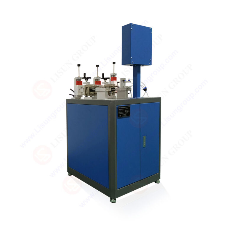
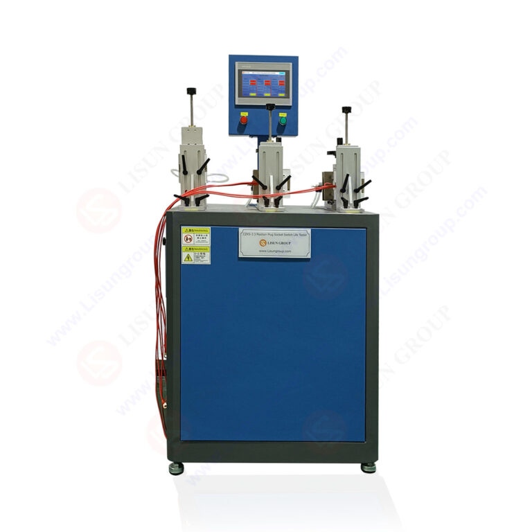
Accurate calibration of the LISUN CZKS-3 series plug and switch durability tester is critical for ensuring compliance with international electrical safety standards such as IEC 60884-1 and IEC 60669-1. This article provides a comprehensive, step-by-step calibration guide for electrical component testing laboratories and quality control engineers. The CZKS-3 tester, along with its variants CZKS-3P, CZKS-3S, and CZKS-3A, is designed for automated durability testing of plugs, sockets, switches, and automotive electrical components. The calibration process described here covers mechanical alignment verification, electrical parameter adjustment, timing accuracy confirmation, and load circuit validation. Proper calibration directly impacts test repeatability, measurement traceability, and certification acceptance for manufacturers seeking compliance with IEC 61058-1 and GB/T 2099.1 standards. This guide transforms complex calibration procedures into actionable technical workflows.
1.1 Calibration Principles and Compliance Framework
Calibration of the LISUN CZKS-3 series involves systematically comparing the tester’s output parameters against reference standards traceable to national metrology institutes. The primary calibration objectives include verifying insertion force accuracy within ±0.1N, confirming contact resistance measurement tolerance below 5mΩ, and ensuring timing sequence precision within ±10ms. These tolerances align with the requirements specified in IEC 60884-1 Clause 20 for mechanical endurance testing and IEC 60669-1 Clause 17 for switch life cycle verification. The calibration process must account for the cylinder-driven actuation mechanism unique to the CZKS-3 platform, which directly influences test repeatability for plug/socket breaking capacity testing.
1.2 Required Calibration Equipment and Reference Standards
Before initiating calibration procedures, engineers must assemble a calibrated force gauge with 1000N capacity and 0.01N resolution, a digital oscilloscope with 100MHz bandwidth for timing measurements, a precision LCR meter for contact resistance verification, and certified reference resistors ranging from 0.1Ω to 100kΩ. The calibration setup requires temperature stabilization at 23°C ±2°C with relative humidity below 60% RH to minimize environmental drift. All reference instruments should possess current calibration certificates with uncertainty budgets below one-third of the CZKS-3 tester’s specified tolerances. This equipment configuration enables complete validation of both mechanical and electrical test parameters.
2.1 Actuator Position and Travel Verification
The CZKS-3 tester employs pneumatic cylinders for plug insertion and switch actuation, requiring precise positional calibration to maintain consistent force application angles. Begin by removing protective covers and inspecting the linear guide rails for contamination. Using a digital dial indicator with 0.01mm resolution, measure actuator travel distance at minimum and maximum stroke settings across three consecutive cycles. The CZKS-3P variant, designed for push-button switches, requires actuator alignment within 0.2mm perpendicular to the test specimen mounting plane. Document deviations exceeding 0.5mm and adjust pneumatic flow control valves to correct travel overshoot before proceeding.
2.2 Insertion Force Calibration for Socket Testing
Socket insertion force calibration demands a dedicated calibration fixture simulating standard plug geometries per IEC 60884-1 Figure 2. Mount the force gauge directly on the actuator arm and program the CZKS-3A to execute 10 insertion cycles at 10N, 30N, and 75N force setpoints. Record peak force values for each cycle and calculate mean deviation from the programmed value. Acceptable calibration limits require force accuracy within ±2% of setpoint for all ranges. For automotive connector applications requiring higher insertion forces up to 150N, the CZKS-3S variant incorporates reinforced actuator assemblies that demand separate calibration verification using a 200N-rated force transducer.
3.1 Cycle Period and Dwell Time Validation
Timing accuracy directly affects durability test results and compliance with IEC 61058-1 Clause 15 for switch endurance testing. Configure the CZKS-3 controller to execute test sequences with 1-second, 5-second, and 30-second cycle periods. Connect the oscilloscope probes across the actuator position sensor output and the load circuit voltage terminals. Measure the time between actuator contact closure and load circuit energization, recording any discrepancies. The CZKS-3 system must maintain timing accuracy within ±10ms for periods below 10 seconds and ±1% for longer durations. Adjust the PLC timing parameters using the manufacturer-approved calibration software interface.
3.2 Interlock and Safety Timing Calibration
Safety interlock testing timing requires separate verification to ensure operator protection during automated testing sequences. Activate the emergency stop while the actuator is in motion and measure the response time between stop signal initiation and complete actuator arrest. The CZKS-3 series must achieve stop times below 100ms per IEC 60204-1 safety requirements. Additionally, verify door interlock delay timing by opening the test chamber during an active cycle; the system should pause within 50ms and display a clear alarm status. Document all timing measurements in the calibration log for audit trail compliance.
4.1 Resistive Load Verification
The CZKS-3 tester’s built-in resistive load banks require periodic calibration to maintain test condition repeatability. Using a calibrated power analyzer, measure actual current draw across each load resistor at 110VAC, 220VAC, and 277VAC test voltages. Compare measured values against programmed load settings of 1A, 5A, 10A, and 16A. The calibration acceptance criterion demands current accuracy within ±3% of setpoint across the full voltage range. For the CZKS-3P variant supporting 20A test currents, verify additional load tap settings using a dedicated 30A-rated current shunt. Replace any resistor elements showing drift exceeding 5% from nominal values.
4.2 Inductive and Capacitive Load Simulation
Standard inductive load simulation for IEC 60884-1 breaking capacity testing requires calibration verification using a reference RL circuit with measured power factor of 0.6 ±0.05. Program the CZKS-3 to apply inductive loads at 5A and 10A levels, then use the power analyzer to confirm both current magnitude and phase angle. Capacitive load calibration for electronic switch testing demands verification of inrush current characteristics; measure peak current values during initial 10ms of contact closure and compare against expected values per IEC 60669-1 Annex B specifications. The CZKS-3S variant includes programmable inrush current limiting that must demonstrate consistent activation at preset thresholds.
5.1 Four-Wire Kelvin Connection Validation
Accurate contact resistance measurement is essential for detecting contact degradation during durability testing. Calibrate the CZKS-3’s internal resistance measurement system using precision resistors of 1mΩ, 10mΩ, 100mΩ, and 1Ω with four-wire Kelvin connections. Connect reference resistors directly to the test fixture terminals to eliminate lead resistance errors. Measure each reference value ten times and calculate mean accuracy and standard deviation. Acceptable calibration limits require measurement error below ±0.5mΩ for values under 10mΩ and ±5% for higher ranges. The CZKS-3A variant, optimized for automotive connector testing, requires additional verification at 0.1mΩ resolution.
5.2 Temperature Compensation Calibration
Contact resistance measurements exhibit significant temperature dependence requiring compensation algorithms calibration. Place a calibrated thermocouple near the test specimen mounting area and record system temperature readings against a reference thermometer at 20°C, 25°C, and 30°C ambient conditions. Program the CZKS-3 controller with known temperature coefficients and verify that corrected resistance values match calculated theoretical values within ±2%. Document compensation curve parameters and verify that the system correctly applies copper conductor temperature coefficients of 0.00393/°C per IEC 60028 standards. Temperature compensation accuracy directly impacts the validity of long-duration endurance test data.
6.1 Analog-to-Digital Converter Linearity Verification
The CZKS-3 series utilizes multi-channel data acquisition systems for recording test parameters including force, displacement, current, voltage, and contact resistance. Verify ADC linearity by applying known reference voltages from a calibrated voltage source across the full input range of ±10V. Measure digital output codes at 20 equally spaced voltage increments and calculate deviation from ideal straight-line response. Acceptable linearity error must remain below 0.1% of full scale. For the CZKS-3P variant supporting 16-bit resolution channels, verify that the least significant bit corresponds to the manufacturer-specified voltage resolution of 0.3mV.
6.2 Timestamp Accuracy and Data Integrity Validation
Test data timestamping accuracy affects the ability to correlate contact failure events with specific cycle counts. Synchronize the CZKS-3 system clock with an NTP time server and then log test data for a 24-hour continuous run. Compare system-generated timestamps against an independent reference timer with millisecond resolution. Acceptable drift must not exceed 1 second over 24 hours. Additionally, verify data logging continuity by disconnecting and reconnecting the communication cable during active testing; the system must buffer at least 1000 data points and resume logging without data loss. This validation ensures reliable audit trail generation for certification submissions.
7.1 Test Sequence Compliance with IEC 60884-1
After completing calibration, execute a full compliance verification test sequence per IEC 60884-1 Clause 20 for plug and socket durability. Program the CZKS-3 to perform 5000 insertion cycles at 100N insertion force with 10A resistive load. Monitor contact resistance at 100-cycle intervals and verify that the system correctly identifies failure conditions when resistance exceeds 100mΩ threshold. Compare recorded parameters against standard requirements including insertion force timing, dwell periods, and load application sequence. The CZKS-3S variant includes pre-programmed compliance test profiles that automatically validate against IEC 60884-1, IEC 60669-1, and IEC 61058-1 requirements.
7.2 Calibration Certificate Generation and Traceability
Generate a comprehensive calibration certificate using the CZKS-3’s built-in reporting module. The certificate must include all calibration results, measurement uncertainty calculations, reference standard identification numbers, environmental conditions during calibration, and a clear pass/fail determination for each parameter. Ensure that measurement uncertainty values include contributions from reference standards, measurement repeatability, and resolution limitations. Maintain calibration records for a minimum of three years per ISO/IEC 17025 requirements. The CZKS-3A variant provides automated certificate generation with digital signature capability for electronic record keeping.
Proper calibration of the LISUN CZKS-3 series is fundamental to achieving reliable, repeatable, and compliant durability testing results for electrical components. This step-by-step guide has addressed mechanical alignment, timing sequences, electrical loads, contact resistance measurements, data acquisition, and standard compliance verification. The CZKS-3, CZKS-3P, CZKS-3S, and CZKS-3A variants each require specific attention to their unique calibration parameters, from automotive connector testing to push-button switch durability. Adherence to these calibration procedures ensures that test results withstand scrutiny during certification audits and provide defensible evidence of product compliance with IEC 60884-1, IEC 60669-1, IEC 61058-1, and GB/T 2099.1 standards. Regular calibration at intervals not exceeding 12 months, combined with daily verification checks, maintains measurement traceability and protects the significant investment in automated test equipment. Manufacturers and testing laboratories that implement these calibration practices achieve higher test repeatability, reduced false failure rates, and increased confidence in their product certification processes. The structured approach outlined here transforms complex calibration requirements into manageable, verifiable procedures that support quality assurance objectives across the electrical components industry.
Q1: What is the recommended calibration interval for the LISUN CZKS-3 series testers?
A: For standard laboratory environments maintaining 23°C ±2°C and below 60% RH, full calibration should be performed at 12-month intervals. However, higher usage rates exceeding 50,000 test cycles per month necessitate semi-annual calibration to maintain measurement traceability. Daily verification checks using reference resistors and force gauges are strongly recommended before each test series. Any observed drift beyond 50% of specified tolerances between scheduled calibrations indicates potential component wear or environmental instability requiring immediate recalibration. The CZKS-3P variant used for high-frequency switch testing may require quarterly calibration due to accelerated mechanical wear on actuation components.
Q2: How does the calibration process differ between the CZKS-3 base model and the CZKS-3S variant?
A: The CZKS-3 base model requires standard mechanical and electrical calibration as described in this guide, while the CZKS-3S variant includes additional calibration steps for its reinforced actuator system and programmable inrush current limiting circuits. The CZKS-3S supports higher test currents up to 20A and requires verification of both normal and high-current load banks. Additionally, the CZKS-3S incorporates specialized timing sequences for semiconductor switch testing that demand oscilloscope-based validation at 1μs resolution. Force calibration for the CZKS-3S uses a 200N-rated force transducer rather than the 100N unit sufficient for the base model. Always reference the specific variant calibration manual provided by LISUN for variant-specific procedures.
Q3: What are the most common calibration failures observed with CZKS-3 testers and their root causes?
A: The most frequent calibration failures include insertion force deviation beyond ±2%, contact resistance measurement drift exceeding ±1mΩ, and timing sequence errors greater than ±15ms. Insertion force drift typically results from pneumatic cylinder seal wear or pressure regulator instability, requiring replacement of sealing components and recalibration of pressure control valves. Contact resistance drift often originates from test fixture connector oxidation or internal relay contact degradation; cleaning with isopropyl alcohol and cycling relays 100 times typically restores accuracy. Timing errors frequently trace to PLC clock crystal aging or electromagnetic interference from adjacent high-power equipment; installing ferrite chokes on power cables and verifying clock synchronization resolves most timing issues.
Q4: Can the CZKS-3 tester be calibrated without removing it from the production testing line?
A: Yes, the CZKS-3 series supports on-site calibration using the built-in calibration mode accessible through the touchscreen interface. This mode disables safety interlocks and allows direct actuator control for calibration procedures while keeping the tester connected to factory network systems. However, initial full calibration after installation or following major repairs should be performed in a controlled metrology laboratory environment. On-site calibration is suitable for interim verification checks but cannot replace the comprehensive calibration required for ISO/IEC 17025 accreditation. The CZKS-3A variant includes a portable calibration fixture that simplifies in-situ calibration of automotive connector test parameters.
Q5: How do environmental conditions affect CZKS-3 calibration stability and what precautions are necessary?
A: Temperature variations exceeding ±2°C cause measurable drift in contact resistance measurements (approximately 0.4% per °C for copper conductors) and pneumatic actuator force output (approximately 1.5% per °C due to gas density changes). Humidity above 70% RH increases leakage currents across test fixtures and compromises insulation resistance measurements. Recommended environmental controls include maintaining laboratory temperature at 23°C ±1°C, relative humidity below 55% RH, and limiting air velocity below 0.5 m/s near the tester. Allow a minimum 2-hour stabilization period after any significant environmental change before performing calibration. The CZKS-3S variant includes built-in temperature sensors that automatically compensate for environmental drift, but these sensors themselves require annual calibration verification.