









Abstract
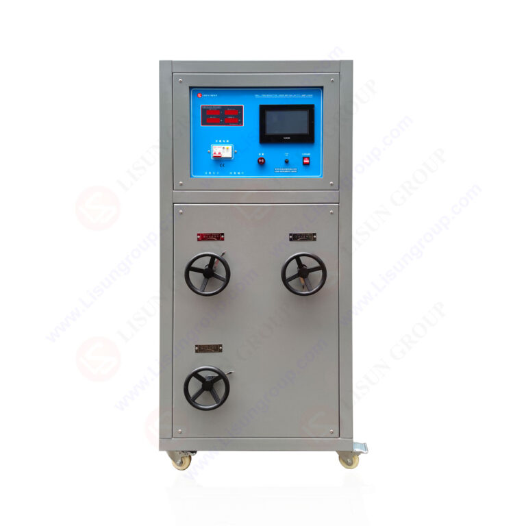
The LISUN DFX series Externally Ballasted Fluorescent Lamp Test Load Cabinet represents a specialized solution for combined life and load testing of power cords and electrical accessories. This article examines the technical specifications, compliance capabilities, and practical applications of the DFX series, focusing on its role in simulating realistic electrical loads during endurance testing. Designed to meet stringent IEC and GB standards, the DFX series enables precise resistive, inductive, and capacitive load simulation with power factor adjustment from 0.3 to 1.0. For electrical product manufacturers, third-party testing laboratories, and quality control engineers, this load test cabinet provides essential functionality for verifying product safety and reliability under continuous operational stress.
1.1 Core Operating Principles
The LISUN DFX series employs externally ballasted fluorescent lamp technology to create precise and repeatable electrical load conditions. Unlike conventional resistive load banks, the DFX series incorporates inductive ballasts that accurately simulate the dynamic characteristics of real-world lighting and appliance loads. This approach ensures that power cords undergo testing under conditions that closely mirror actual field usage.
The load simulation mechanism operates by combining resistive heating elements with inductive ballasts and capacitive components, allowing operators to configure specific power factor values. The system achieves power factor adjustments from 0.3 lagging to 1.0 unity, with a resolution of 0.01, enabling fine-grained control over test parameters.
1.2 Model Variants and Configuration Options
The DFX series encompasses five distinct models, each tailored to specific testing capacity requirements. The following table presents the core specifications across the product range:
| Model | Current Output Range (A) | Channel Count | Input Voltage (V) | Maximum Power (kVA) | Power Factor Range |
|---|---|---|---|---|---|
| DFX-20 | 0.1 – 20.0 | 1 | 220 AC | 4.4 | 0.3 – 1.0 |
| DFX-20-3CH | 0.1 – 20.0 | 3 | 380 AC | 13.2 | 0.3 – 1.0 |
| DFX-40 | 0.1 – 40.0 | 1 | 220 AC | 8.8 | 0.3 – 1.0 |
| DFX-60 | 0.1 – 60.0 | 1 | 220 AC | 13.2 | 0.3 – 1.0 |
| DFX-80 | 0.1 – 80.0 | 1 | 380 AC | 17.6 | 0.3 – 1.0 |
The DFX-20-3CH model offers three independent channels, making it suitable for simultaneous testing of multiple power cord samples. Higher current models such as the DFX-60 and DFX-80 accommodate heavy-duty power cords rated for industrial applications.
2.1 IEC and GB Standard Alignment
The LISUN DFX series is engineered to fulfill the testing requirements specified in multiple international standards. Key compliance areas include:
IEC 60669-1 Clause 19.2 – Switches for household and fixed electrical installations: This clause mandates endurance testing under rated current and power factor conditions. The DFX series provides the necessary load simulation to verify switch contact performance through 10,000 to 50,000 operational cycles.
IEC 60884-1 Clause 20 – Plugs and socket-outlets for household and similar purposes: This clause specifies the electrical endurance test for plugs and sockets, requiring testing at rated current with specific power factor values. The DFX series enables precise replication of these conditions across multiple test cycles.
GB 2099.1 Clause 21 – Plugs and socket-outlets for household and similar purposes: Equivalent to IEC 60884-1, this Chinese national standard requires similar load testing parameters, and the DFX series provides full compliance capability.
IEC 60320-1 Clause 14 – Appliance couplers for household and similar general purposes: This standard specifies the thermal and endurance testing requirements for appliance couplers, where combined life and load testing using the DFX series ensures accurate simulation of operational stresses.
2.2 Verification Against Minimum Standard Requirements
The following table compares the LISUN DFX series capabilities against the minimum requirements specified in IEC 60669-1 and IEC 60884-1:
| Parameter | IEC 60669-1 Requirement | IEC 60884-1 Requirement | LISUN DFX Capability |
|---|---|---|---|
| Current Accuracy | ±5% of set value | ±5% of set value | ±1% of set value |
| Power Factor Range | 0.6 – 0.95 | 0.6 – 0.95 | 0.3 – 1.0 |
| Minimum Test Cycles | 10,000 | 10,000 | Unlimited (cyclic) |
| Load Type | Mixed resistive/inductive | Mixed resistive/inductive | Fully adjustable RLC |
| Voltage Stability | ±3% | ±3% | ±1% |
The DFX series exceeds minimum standard requirements in current accuracy and power factor range, providing a safety margin that enhances test reliability and reproducibility.
3.1 Resistive, Inductive, and Capacitive Load Configuration
The DFX series supports three fundamental load types that can be combined to create complex test conditions. Resistive loads simulate pure heating elements, inductive loads represent motor-driven appliances, and capacitive loads account for electronic power supplies with power factor correction circuits.
The load configuration is achieved through a combination of internally mounted ballasts and external components. Operators can select pre-configured load profiles or customize parameters using the front panel controls. The system supports load capacitance values ranging from 0.1 μF to 100 μF, enabling simulation of modern electronic loads.
3.2 Power Factor Adjustment Precision
Power factor adjustment is a critical parameter for combined life and load testing because it directly affects the stress imposed on power cord contacts and insulation. The DFX series achieves power factor adjustment through a variable inductor arrangement that modifies the phase angle between voltage and current waveforms.
The adjustment mechanism provides a resolution of 0.01 across the entire 0.3 to 1.0 range. This precision allows test engineers to replicate specific load conditions required by different product categories. For example, IEC 60669-1 requires testing at power factors of 0.6 and 0.95, both of which can be set within seconds using the DFX series digital control interface.
Measurement accuracy for power factor is maintained within ±0.02 of the set value, ensuring that test conditions remain consistent throughout extended endurance testing sessions that may last for several days.
4.1 LISUN CZKS Series Life Testers
The DFX series load test cabinet is designed to work seamlessly with the LISUN CZKS series life testers, creating a comprehensive combined life and load testing system. The CZKS series provides the mechanical actuation and cycle counting required for endurance testing, while the DFX series supplies the electrical load.
In a typical configuration, the CZKS life tester controls the switching mechanism of the power cord or electrical accessory under test. Each operation cycle triggers the DFX series to apply the specified electrical load. The CZKS system records the number of cycles completed and can automatically stop the test when the preset cycle count is reached.
This integration eliminates the need for separate control systems and ensures synchronized operation between mechanical and electrical test components. The combined system can run unattended for extended periods, with automatic fault detection and shutdown capabilities.
4.2 LISUN SW-6 Bending Testers
For power cord testing that requires mechanical stress in addition to electrical loading, the DFX series integrates with the LISUN SW-6 bending tester. The bending tester subjects power cords to repeated flexing at specified angles, simulating real-world usage conditions such as cord strain at the entry point of appliances.
During combined testing, the SW-6 bending tester applies mechanical stress while the DFX series maintains continuous electrical load. This combined stress testing reveals failure modes that might not appear during separate electrical or mechanical testing.
The system monitors continuity and insulation resistance throughout the test, immediately detecting any interruption or degradation. This capability is essential for compliance with standards such as IEC 60320-1 that require testing under combined mechanical and electrical stress.
5.1 Digital Control and Monitoring Systems
The DFX series incorporates a digital control system that provides real-time monitoring of all test parameters. The front panel display shows voltage, current, power factor, active power, and test duration. Operators can set test parameters using the membrane keypad and rotary encoder, with all settings stored in non-volatile memory.
The control system includes programmable test sequences that allow operators to define multiple load conditions for a single test. For example, a test sequence might include 8 hours at rated current with 0.6 power factor, followed by 8 hours at 1.2 times rated current with unity power factor. This capability is particularly valuable for accelerated life testing protocols.
5.2 Safety Features and Protection Systems
Safety is paramount in electrical load testing, and the DFX series incorporates multiple protection systems. Overcurrent protection automatically disconnects the load if current exceeds the set limit by 10%. Thermal protection monitors internal component temperatures and reduces load or shuts down the system if thresholds are exceeded.
Ground fault detection continuously monitors leakage current to ground, ensuring operator safety and preventing damage to test samples. The system also includes emergency stop buttons and remote shutdown capability for integration with automated test systems.
These safety features are particularly important during combined life and load testing sessions that may run continuously for 1,000 hours or more without operator supervision.
6.1 Power Cord Manufacturing Quality Assurance
Power cord manufacturers use the DFX series to perform incoming quality control on raw materials and final product verification. The combined life and load testing capability allows manufacturers to verify that cords meet the required current-carrying capacity and insulation integrity under sustained load.
For example, a manufacturer producing cords rated for 10 A at 250 V can use the DFX-20 to test samples at 1.25 times rated current for 1 hour, followed by 10,000 cycles of switching at rated current. This testing protocol, specified in IEC 60884-1, verifies that the cord can withstand both thermal stress and mechanical switching wear.
6.2 Third-Party Testing Laboratory Certification
Testing laboratories certified to perform compliance testing rely on the DFX series for its accuracy and repeatability. The system’s ability to maintain stable load conditions over extended periods ensures that test results are reproducible and defensible during certification audits.
Laboratories benefit from the multi-channel capability of the DFX-20-3CH, which allows simultaneous testing of up to three samples under identical conditions. This parallel testing capability increases throughput while maintaining the precision required for certified testing.
7.1 Periodic Calibration Procedures
The DFX series requires periodic calibration to maintain its specified accuracy. Calibration intervals are typically 12 months, although laboratories conducting high-volume testing may require more frequent calibration. The calibration process verifies current output accuracy, power factor adjustment precision, and voltage measurement accuracy.
Calibration is performed using traceable reference standards, and the system includes self-diagnostic routines that check internal components before each test session. The DFX series stores calibration data in non-volatile memory, and the system automatically applies correction factors to maintain accuracy between calibrations.
7.2 Component Replacement and Service Intervals
Key components in the DFX series have defined service intervals. The externally ballasted fluorescent lamps, which provide the inductive load component, have a typical service life of 5,000 operating hours. These components are field-replaceable, minimizing downtime.
Cooling fans and filters should be inspected monthly and replaced as needed to maintain proper thermal management. The system’s internal relays and contactors, which switch load configurations, have a rated life of 100,000 operations and should be inspected annually.
The LISUN DFX series Externally Ballasted Fluorescent Lamp Test Load Cabinet provides a technically robust solution for combined life and load testing of power cords and electrical accessories. With precise power factor adjustment from 0.3 to 1.0, current output ranges up to 80 A, and compliance with IEC 60669-1, IEC 60884-1, GB 2099.1, and IEC 60320-1 standards, the DFX series enables testing laboratories and manufacturers to conduct accurate, repeatable endurance tests. Integration with the LISUN CZKS life testers and SW-6 bending testers creates a comprehensive testing workflow that addresses both electrical and mechanical stress requirements. The system’s digital control interface, real-time monitoring, and extensive safety features support both routine quality assurance and certification testing applications. For organizations committed to producing compliant, reliable power cords and electrical accessories, the DFX series represents a technically sound investment in testing infrastructure.
Q1: What is the difference between combined life and load testing and standard life testing for power cords?
A: Standard life testing typically involves cycling a power cord or electrical accessory under no-load or low-load conditions, primarily testing mechanical endurance. Combined life and load testing, as performed using the LISUN DFX series, applies rated (or higher) electrical current and specified power factor conditions during each operational cycle. This combined approach subjects the power cord to both thermal stress from current flow and mechanical stress from switching operations. The thermal stress accelerates contact degradation mechanisms such as oxidation and material transfer, while the mechanical stress tests the cord’s ability to withstand repeated flexing and movement. Combined testing more accurately simulates real-world usage conditions and reveals failure modes that would not appear during separate electrical or mechanical testing.
Q2: How does the LISUN DFX series achieve power factor adjustment without mechanical components?
A: The DFX series uses an arrangement of externally ballasted fluorescent lamps combined with precision variable inductors to achieve power factor adjustment. The fluorescent lamp ballasts inherently introduce inductive reactance into the load circuit, while additional variable inductor modules allow fine-tuning of the inductance value. By adjusting the ratio of resistive to inductive components in the load circuit, the system changes the phase angle between voltage and current waveforms. Unlike mechanical variable transformers, this approach uses solid-state switching for load configuration, resulting in faster response times and higher reliability. The system also incorporates fixed capacitor banks that can be switched in or out to achieve leading power factors when required for specific test standards. The entire adjustment process is controlled digitally, with the microprocessor continuously monitoring the actual power factor and making corrections to maintain the set value.
Q3: Can the DFX series be used for testing other electrical accessories besides power cords?
A: Yes, the DFX series is designed for testing a wide range of electrical accessories beyond power cords. These include switches (per IEC 60669-1), plugs and socket-outlets (per IEC 60884-1), appliance couplers (per IEC 60320-1), connectors, and terminal blocks. The key requirement is that the accessory being tested must have a rated current within the DFX series output range. The load type (resistive, inductive, or capacitive) and power factor can be configured to match the specific accessory’s application. For example, motor-rated switches require inductive loads, while heating appliance switches require resistive loads. The DFX series’ ability to switch between load configurations without physical reconfiguration makes it suitable for laboratories that test multiple product types. Additionally, the multi-channel DFX-20-3CH model enables simultaneous testing of different accessories or multiple samples of the same accessory.
Q4: What maintenance procedures are required to keep the DFX series operating at specified accuracy?
A: Maintaining the DFX series at specified accuracy requires a structured maintenance program. Annual calibration is the most critical procedure, during which all current, voltage, and power factor measurements are verified against traceable standards. Monthly inspections should include checking cooling fan operation and cleaning air filters to prevent overheating. The externally ballasted fluorescent lamps, which typically have a 5,000-hour service life, should be replaced before reaching end-of-life to maintain consistent inductive load characteristics. Internal connections and power terminals should be inspected annually for signs of overheating or corrosion. The system’s self-diagnostic routines should be run before each test session to verify internal component functionality. If the system is used for high-volume testing or in harsh environments, more frequent maintenance intervals may be necessary. All maintenance activities should be documented in a log for quality assurance and audit purposes.
Q5: How does the DFX series ensure consistent load conditions during extended endurance tests that last several days?
A: The DFX series maintains consistent load conditions through several integrated mechanisms. First, the digital control system uses closed-loop feedback to continuously monitor actual output current and power factor, making real-time adjustments to compensate for thermal drift or component aging. Second, the system’s thermal management design includes oversized heat sinks and forced-air cooling that maintain internal components within their specified temperature range, minimizing resistance changes due to temperature variation. Third, the externally ballasted fluorescent lamps have stable impedance characteristics over their operating life, unlike wire-wound resistors that can exhibit significant drift. Fourth, the system includes voltage regulation circuitry that compensates for fluctuations in the input power supply. During extended tests, the control system logs all parameters at programmable intervals, allowing operators to verify that conditions remained within tolerance throughout the test duration. If any parameter exceeds specified limits, the system can automatically stop the test and record the failure point.