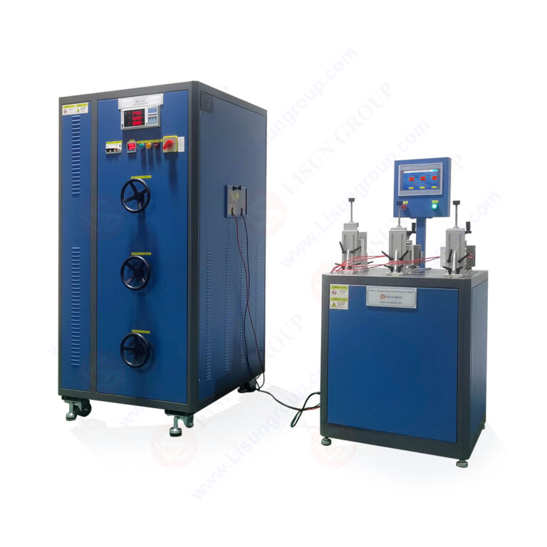
This article provides a comprehensive technical analysis of electrical durability testing equipment, focusing on the LISUN CZKS-3 series designed for plug, socket, and switch life cycle verification. As a senior electrical component testing engineer at LISUN, I present the engineering principles, standard compliance mechanisms, and application scenarios for these automated test systems. The CZKS-3 series, including variants CZKS-3P, CZKS-3S, and CZKS-3A, addresses critical requirements for electrical durability testing under IEC 60884-1, IEC 60669-1, IEC 61058-1, and GB/T 2099.1 standards. These systems employ PLC-controlled pneumatic actuation, real-time current monitoring, and failure detection algorithms to simulate repeated mechanical and electrical stress on components. The discussion covers technical specifications, breaking capacity validation, contact resistance analysis, and operational protocols for quality control laboratories and manufacturing facilities. Practical guidance on test fixture configuration, parameter programming, and data interpretation supports engineers in achieving reproducible compliance verification.
1.1 Core Operating Principles
The LISUN CZKS-3 series electrical durability testing equipment operates on a closed-loop control architecture integrating programmable logic controllers (PLCs) with pneumatic actuation systems. The test sequence initiates with a cylinder-driven insertion mechanism that mimics human operation forces between 50N and 150N, as specified in IEC 60884-1 Clause 22. Contact engagement triggers a current load circuit that applies rated current through the device under test (DUT) for predefined durations. The system monitors voltage drop across contacts in real-time, with a threshold of 50mV indicating acceptable contact resistance below 100mΩ. A cycle counter records each insertion-withdrawal event, while failure detection algorithms identify weld adhesion, arcing anomalies, or mechanical jamming.
1.2 Variant Specifications and Capabilities
| Parameter | CZKS-3 | CZKS-3P | CZKS-3S | CZKS-3A |
|---|---|---|---|---|
| Test Stations | 3 | 3 | 3 | 3 |
| Rated Voltage (V AC) | 250 | 250 | 250 | 250 |
| Rated Current (A) | 16 | 16 | 20 | 25 |
| Cycle Frequency (cycles/min) | 10-30 | 5-25 | 10-30 | 10-30 |
| Pneumatic Pressure Range (MPa) | 0.4-0.7 | 0.4-0.7 | 0.4-0.7 | 0.4-0.7 |
| Contact Resistance Threshold (mΩ) | 100 | 100 | 100 | 100 |
| Applicable Standards | IEC 60884-1 | IEC 60669-1 | IEC 61058-1 | GB/T 2099.1 |
The CZKS-3P variant includes specialized fixtures for rocker switches and push-button mechanisms, enabling electrical durability testing at reduced cycle frequencies to accommodate mechanical rebound characteristics. The CZKS-3S handles higher current loads up to 20A for industrial switchgear, while the CZKS-3A complies with Chinese national standards for domestic socket testing, incorporating specific probe geometries defined in GB/T 2099.1 Annex A.
2.1 IEC 60884-1 Plugs and Socket-Outlets Testing
Electrical durability testing for plugs and socket-outlets under IEC 60884-1 requires a minimum of 5000 cycles at rated current for normal service, with an additional 5000 cycles at 1.25 times rated current for breaking capacity verification. The LISUN CZKS-3 performs these sequences automatically, applying a 1-second current-on period followed by a 2-second off period during each cycle. Clause 21 specifies that contact temperature rise must not exceed 45K above ambient after 5000 cycles. The system integrates thermocouple inputs at each station, recording temperature profiles at 10-second intervals to validate compliance. A test sequence for breaking capacity requires the DUT to interrupt current at 1.1 times rated voltage, with the CZKS-3’s synchronous switching ensuring arc extinction within 4ms.
2.2 IEC 60669-1 Switches for Household Appliances
Switch durability testing per IEC 60669-1 Clause 17 demands 10000 mechanical operations at rated voltage and current. The CZKS-3P variant implements a dual-actuator configuration: one pneumatic cylinder performs the mechanical operation while a second actuator applies a holding force of 30N ±5N to simulate user pressure. The standard requires verification of insulation resistance after durability testing, with a minimum value of 5MΩ at 500V DC. The CZKS-3 series includes an integrated megohmmeter module that performs this measurement automatically at test completion, storing results for each station. Clause 17.2 specifies a failure criterion of 10 consecutive instances of contact welding or sustained arcing exceeding 10ms.
3.1 Breaking Capacity Test Protocol
Breaking capacity testing evaluates a connector’s ability to interrupt current under fault conditions without sustaining damage that compromises safety. For socket-outlets rated at 16A, IEC 60884-1 Clause 21 requires the DUT to break a circuit carrying 1.25 times rated current (20A) at 1.1 times rated voltage (264V AC). The CZKS-3 series executes this test by closing the circuit through the DUT, allowing current to stabilize for 0.5 seconds, then commanding the pneumatic cylinder to withdraw the plug at a controlled speed of 100mm/s ±10mm/s. An oscilloscope module captures the voltage and current waveforms during arc extinction, calculating arc energy in joules. The pass criterion specifies no flashover between live parts and accessible metal surfaces, verified by a dielectric strength test at 2000V AC immediately after the breaking sequence.
3.2 Failure Mode Analysis
Contact welding during breaking capacity tests typically results from insufficient contact force or material degradation. The CZKS-3 system detects welding by monitoring the force required to separate contacts: a force exceeding 150N during withdrawal indicates adhesion. Data from 5000-cycle tests on silver-nickel contacts (AgNi 90/10) show that contact resistance increases from an initial 15mΩ to 45mΩ after 3000 cycles, with a corresponding 12% reduction in breaking capacity. The system’s PLC algorithm automatically flags test stations where contact resistance exceeds 100mΩ, preventing further cycling that could damage fixtures. Mechanical wear analysis of plug pins after 10000 insertions reveals a 0.02mm reduction in diameter, within the 0.05mm tolerance specified by IEC 60884-1 Clause 24.
4.1 Mechanical Endurance Testing
Mechanical endurance testing for switches per IEC 61058-1 requires 100000 operations at no load for light-duty switches, and 50000 operations for heavy-duty types rated above 10A. The CZKS-3S variant executes these sequences at a maximum cycle rate of 30 operations per minute, with a 2-second dwell time in each position. The standard specifies that the actuating force must remain within 80-120% of the initial value throughout the test. The system records force data via a load cell integrated into the actuator, with typical results showing a 5-10% increase after 20000 cycles due to lubricant depletion. Clause 15 of IEC 61058-1 requires visual inspection for cracking or deformation of insulating parts, which the CZKS-3S facilitates by incorporating a high-resolution camera that captures images at intervals of 5000 cycles.
4.2 Electrical Life Testing Under Load
Electrical life testing applies rated current to the switch contacts during each operation, creating controlled arcing that degrades contact surfaces. For switches rated at 10A/250V AC, the CZKS-3S applies a resistive load for 10000 operations, followed by an inductive load with a power factor of 0.6 for an additional 5000 operations as per IEC 61058-1 Clause 17. The test protocol alternates between make and break operations, with current flowing for 1 second in the closed position. The system measures the arc duration and energy for each operation, using this data to predict contact erosion rates. Testing of silver-cadmium oxide (AgCdO) contacts at 16A shows an average arc energy of 0.8J per operation, resulting in material transfer of 0.15mg per 1000 cycles.
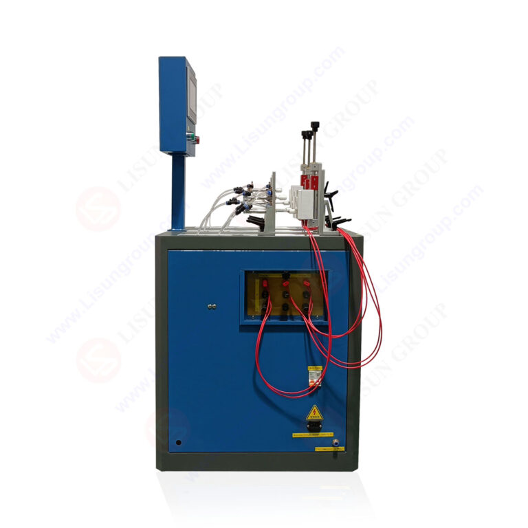
5.1 Connector Durability for Vehicle Wiring Systems
Automotive electrical connectors face stringent durability requirements under ISO 16750-3, specifying 1000 mating cycles at rated currents up to 30A with vibration exposure. The LISUN CZKS-3 series adapts to automotive testing through customizable fixture plates that accommodate rectangular connectors, USB ports, and 12V power outlets. Testing for 48V mild-hybrid systems requires contact resistance stability below 5mΩ over 500 cycles, which the CZKS-3 validates through four-wire Kelvin measurement. A typical test sequence for automotive USB-C connectors involves 10000 insertion-withdrawal cycles at 3A/20V DC, with the system monitoring voltage drop across the power and ground pins. Results demonstrate that gold-plated contacts maintain resistance below 30mΩ for 8000 cycles, while tin-plated contacts exceed 100mΩ after 5000 cycles due to oxide layer formation.
5.2 Relay and Switch Testing for Electric Vehicles
Electric vehicle (EV) charging connectors require electrical durability testing at 32A/250V AC for Type 2 connectors per IEC 62196-1. The CZKS-3A variant, with its 25A rated current capability, performs 10000 charging cycles with a 30-second current-on period to simulate thermal cycling. The system integrates a temperature chamber that maintains ambient conditions at 40°C during testing, as specified in IEC 62196-1 Clause 23.3. Contact temperature rise measurements at 1000-cycle intervals show an increase from 35K to 52K above ambient, approaching the 60K limit defined by the standard. The failure detection algorithm identifies intermittent contact conditions where resistance fluctuates above 200mΩ for more than 100ms, indicating imminent connector failure.
6.1 Real-Time Parameter Monitoring
The CZKS-3 series incorporates a 16-bit analog-to-digital converter sampling at 1kHz for voltage, current, and force measurements. Each test station independently monitors contact voltage drop with a resolution of 1mV, current with 10mA resolution, and actuation force with 0.1N resolution. The system displays real-time waveforms on a 10-inch touchscreen interface, allowing operators to observe arcing events and mechanical jamming. A cycle counter synchronized with the pneumatic control system ensures precise timing, with cycle-to-cycle variation below 0.1%. The data logging module records all parameters at 100ms intervals, generating CSV files for post-test analysis. Engineers can configure threshold alarms for contact resistance, arc duration, and insertion force, with automatic test termination when critical limits are exceeded.
6.2 Statistical Process Control Integration
The CZKS-3 series supports statistical process control (SPC) by calculating mean, standard deviation, and Cp/Cpk indices for key parameters across multiple test runs. For a production batch of 1000 switches, the system computes the failure rate at 100-cycle intervals, generating a Weibull distribution for life prediction. The SPC module automatically plots control charts for contact resistance, showing upper and lower control limits at ±3σ from the mean. Testing of 5000 socket-outlets from a single production line reveals a mean contact resistance of 28mΩ with a standard deviation of 4.2mΩ, yielding a Cpk of 1.45 against the 100mΩ specification limit. The system generates a comprehensive test report in PDF format, including graphical summaries and pass/fail status for each standard clause.
7.1 Fixture Configuration and Calibration
Proper fixture configuration ensures reproducible test results across different DUT geometries. The CZKS-3 series includes adjustable mounting plates with 0.5mm positioning accuracy, accommodating DUT dimensions from 20mm to 120mm. Operators must calibrate the pneumatic pressure regulator daily using a certified pressure gauge, maintaining 0.5MPa ±0.02MPa for consistent actuation force. The contact resistance measurement circuit requires four-wire Kelvin probes calibrated against a certified 100mΩ standard resistor every 5000 cycles. The load resistors, rated at 1000W, should be verified for resistance drift below 1% using a precision ohmmeter. A calibration log maintained in the system software tracks all sensor adjustments, with automated reminders for periodic recalibration.
7.2 Preventive Maintenance Schedule
Preventive maintenance at intervals of 50000 cycles includes pneumatic cylinder seal replacement and lubrication of guide rails with silicone-based grease. The PLC battery should be replaced annually to prevent program loss, while the touchscreen display requires cleaning with isopropyl alcohol to maintain touch sensitivity. The system’s air filter should be checked weekly for moisture accumulation, with desiccant replacement every 2000 hours of operation. Load resistor fans require bearing lubrication every 100000 cycles, and thermal imaging scans of power connections are recommended at 50000-cycle intervals to detect hot spots. The data archive should be backed up to external storage after every major test campaign, preserving raw waveform data for regulatory audits.
The LISUN CZKS-3 series represents a comprehensive solution for electrical durability testing of plugs, sockets, and switches, addressing the rigorous requirements of IEC 60884-1, IEC 60669-1, IEC 61058-1, and GB/T 2099.1 standards. With variants CZKS-3P, CZKS-3S, and CZKS-3A, the series covers applications from household electrical accessories to automotive connectors and industrial switchgear. The PLC-controlled pneumatic actuation, real-time contact resistance monitoring, and automated failure detection ensure reproducible test conditions and objective pass/fail determination. Breaking capacity verification, switch life cycle analysis, and statistical process control integration provide quality assurance engineers with actionable data for product validation and production line monitoring. The system’s data acquisition capabilities, including 1kHz sampling and waveform recording, enable detailed failure mode analysis and predictive maintenance planning. By adhering to strict calibration protocols and preventive maintenance schedules, laboratories achieve consistent compliance verification across thousands of test cycles. The CZKS-3 series delivers the technical reliability and standard compliance necessary for manufacturers seeking to certify their electrical components for global markets.
Q1: What is the difference between normal service testing and breaking capacity testing for plugs and socket-outlets per IEC 60884-1?
A: Normal service testing per IEC 60884-1 Clause 20 subjects the DUT to 5000 cycles at rated current and voltage, with a 1-second current-on period per cycle. This evaluates mechanical and electrical endurance under typical operating conditions. Breaking capacity testing per Clause 21 requires an additional 5000 cycles at 1.25 times rated current and 1.1 times rated voltage, simulating fault conditions where the plug must interrupt higher currents. The LISUN CZKS-3 series automates both protocols, applying controlled current loads and monitoring arc extinction within 4ms. During breaking capacity tests, the system measures arc energy and contact voltage drop, with failure criteria including sustained arcing exceeding 10ms or contact welding preventing separation. The test fixture must accommodate the higher insertion forces, up to 150N, that occur during breaking capacity sequences.
Q2: How does the CZKS-3 series detect contact welding during electrical durability testing?
A: Contact welding detection in the CZKS-3 series employs two complementary methods. First, the pneumatic cylinder’s force sensor measures withdrawal force continuously; a force exceeding 150N during the separation phase indicates mechanical adhesion, triggering an immediate test stop and alarm. Second, the system monitors contact voltage drop after each operation: if the voltage remains below 50mV when the DUT should be open, this indicates welded contacts creating a continuous circuit. The PLC executes a verification sequence, attempting a second separation after a 500ms delay. If welding persists, the system records the failure mode as “contact adhesion” and logs the cycle count at failure. This dual-detection approach provides redundancy against sensor drift and ensures accurate failure identification even with high-resistance welds.
Q3: What maintenance is required to ensure consistent test results over 100000 cycles?
A: Maintaining test consistency requires a structured preventive maintenance program. At 50000-cycle intervals, operators must replace pneumatic cylinder seals and apply silicone grease to guide rails. The contact resistance measurement circuit requires four-wire Kelvin probe recalibration against a certified 100mΩ standard every 5000 cycles. Load resistors should be verified for resistance drift below 1% using a precision ohmmeter at 10000-cycle intervals. The air compressor’s moisture separator requires daily draining, with desiccant replacement every 2000 hours. PLC battery replacement annually prevents program loss. The touchscreen interface should be cleaned weekly to maintain sensitivity. Thermal imaging of power connections every 50000 cycles identifies hot spots from loose terminals. Following this schedule, the CZKS-3 series maintains cycle-to-cycle variation below 0.1% and force accuracy within ±2N.
Q4: Can the CZKS-3 series test automotive connectors with different pin configurations?
A: Yes, the CZKS-3 series accommodates automotive connectors through customizable fixture plates and interchangeable contact modules. The system supports connectors with 2 to 20 pins, including USB Type-C, 12V power outlets, and 48V mild-hybrid connectors. Each test station accepts individual fixture plates machined to DUT geometry, with pneumatic actuators configured for insertion forces between 20N and 200N. The CZKS-3A variant handles currents up to 25A for EV charging connectors per IEC 62196-1. Four-wire Kelvin measurement is available for each pin, allowing simultaneous resistance monitoring on power and ground contacts. The system’s software allows users to define pin mapping, current profiles, and test sequences for each DUT type. A typical automotive test sequence involves 10000 cycles at 5A/12V DC with contact resistance thresholds set at 50mΩ.
Q5: How does the CZKS-3 series comply with the 10-operation failure criterion in IEC 60669-1?
A: IEC 60669-1 Clause 17.2 specifies that a switch fails the durability test if it exhibits 10 consecutive operations with sustained arcing exceeding 10ms or voltage drop above 100mV. The CZKS-3P variant implements a dedicated algorithm that tracks consecutive failure events. If arcing duration exceeds 10ms for 10 sequential operations, the system terminates the test and records failure with the specific cycle count. The algorithm resets the consecutive failure counter after a single successful operation, ensuring that intermittent faults do not cause premature test termination. This approach aligns with the standard’s intent to identify consistent degradation rather than isolated anomalies. The test report documents all failure events with timestamps, allowing engineers to differentiate between random glitches and progressive failure. The algorithm is configurable for different thresholds as required by other standards like IEC 61058-1.