









The LISUN DFX series Externally Ballasted Fluorescent Lamp Test Load Cabinet provides a precision solution for electrical product certification laboratories conducting IEC 60598 compliance testing. This equipment simulates resistive, inductive, and capacitive loads with programmable power factor adjustment, enabling accurate evaluation of switches, relays, and connectors under real-world ballasted lamp conditions. The LISUN DFX series Externally Ballasted Fluorescent Lamp Test Load Cabinet delivers current output ranges from 20A to 80A across multiple models, with high-resolution measurement accuracy of ±0.5% for load parameters. For third-party testing facilities and quality control engineers, this load test cabinet streamlines certification workflows by integrating with life testing systems and bending testers, ensuring reproducible results that meet international standard requirements. The article examines technical specifications, compliance validation, and practical integration strategies for laboratory environments.
1.1 Core Load Simulation Principles
The LISUN DFX series employs passive impedance networks with precision switching to replicate fluorescent lamp characteristics. Resistive loads use wire-wound resistors with thermal stability ratings exceeding 200W per element. Inductive loads incorporate laminated core inductors with air gaps to prevent saturation at rated currents. Capacitive loads utilize metallized polypropylene capacitors with dissipation factors below 0.001 at 50Hz. The power factor adjustment range spans 0.3 lagging to 0.9 lagging with resolution of 0.01, enabling simulation of standard ballasted lamp configurations per IEC 60598-1 Annex A.
1.2 Model Variants and Specification Comparison
The DFX series includes five models tailored for different testing capacities. The DFX-20 provides single-channel 20A output for basic switch testing. The DFX-20-3CH offers three independent channels at 20A each for multi-sample testing. Higher-capacity models DFX-40, DFX-60, and DFX-80 deliver 40A, 60A, and 80A respectively on single channels. All models support 220VAC or 380VAC input configurations with automatic voltage stabilization within ±2%.
| Model | Current Output Range | Channels | Input Voltage | Power Factor Range | Load Capacitance Range |
|---|---|---|---|---|---|
| DFX-20 | 0.5A – 20A | 1 | 220VAC ±10% | 0.3 – 0.9 lag | 0 – 150µF |
| DFX-20-3CH | 0.5A – 20A per channel | 3 | 380VAC ±10% | 0.3 – 0.9 lag | 0 – 150µF per channel |
| DFX-40 | 1A – 40A | 1 | 380VAC ±10% | 0.3 – 0.9 lag | 0 – 300µF |
| DFX-60 | 1A – 60A | 1 | 380VAC ±10% | 0.35 – 0.9 lag | 0 – 500µF |
| DFX-80 | 2A – 80A | 1 | 380VAC ±10% | 0.35 – 0.9 lag | 0 – 800µF |
2.1 IEC 60598-1 Clause 12.4 Thermal Testing Requirements
IEC 60598-1 Clause 12.4 specifies thermal endurance testing for luminaires under normal operating conditions with ballasted lamp loads. The DFX series replicates the electrical characteristics of fluorescent lamps with external ballasts, including harmonic current content up to 13% THD as specified in Annex A. The load cabinet maintains stable impedance across 8-hour test cycles within ±0.5% resistance drift, ensuring thermal test reproducibility within 2°C tolerance.
2.2 IEC 60669-1 Clause 19.2 Switch Endurance Validation
IEC 60669-1 Clause 19.2 mandates 10,000 to 50,000 mechanical operations for switches under inductive loads with power factors between 0.6 and 0.8 lagging. The DFX-20-3CH model supports simultaneous testing of three switches, with cyclic counting accuracy of ±1 operation over 100,000 cycles. Integrated overcurrent protection disconnects loads within 5ms when current exceeds set thresholds by 10%, protecting both test samples and equipment.
2.3 IEC 60884-1 Clause 20 Connector Load Testing
IEC 60884-1 Clause 20 requires connectors to withstand rated current plus 10% under resistive-inductive loads with power factor 0.6 ±0.05. The DFX-40 model achieves this with precision power factor resolution of 0.01, allowing operators to set 0.60 exactly. Measurement accuracy for voltage drop across contacts is ±5mV at 40A, enabling detection of 0.125mΩ resistance changes indicative of contact degradation.
3.1 Power Factor Adjustment Mechanisms
The DFX series uses tapped inductor banks with eight selectable inductance values per channel, combined with capacitance switching using solid-state relays rated for 100,000 operations. Inductance values range from 5mH to 200mH in binary-weighted steps, while capacitance ranges from 5µF to 150µF per channel. The combination achieves 128 discrete power factor settings between 0.30 and 0.90 lagging, with accuracy verified against NIST-traceable reference standards.
3.2 Real-Time Parameter Monitoring
Embedded digital instrumentation measures RMS voltage, RMS current, active power, reactive power, and power factor simultaneously. Voltage measurement accuracy is ±0.2% of reading ±0.5V for 100-300VAC ranges. Current accuracy is ±0.5% of reading ±0.1A. Power factor measurement resolution is 0.001 with accuracy of ±0.01. Data logging capability records up to 10,000 test cycles with timestamped parameter snapshots at adjustable intervals from 0.1s to 60s.
4.1 Forced Air Cooling Design
Each load cabinet model incorporates dual axial fans with 120CFM airflow capacity, controlled by PID temperature regulators. Thermal sensors monitor load element temperatures at 12 locations, triggering automatic load reduction if temperatures exceed 85°C. The DFX-80 model additionally includes water-cooled heat sinks for high-current resistive loads, maintaining surface temperatures below 60°C at 80A continuous operation.
4.2 Protection Circuitry Architecture
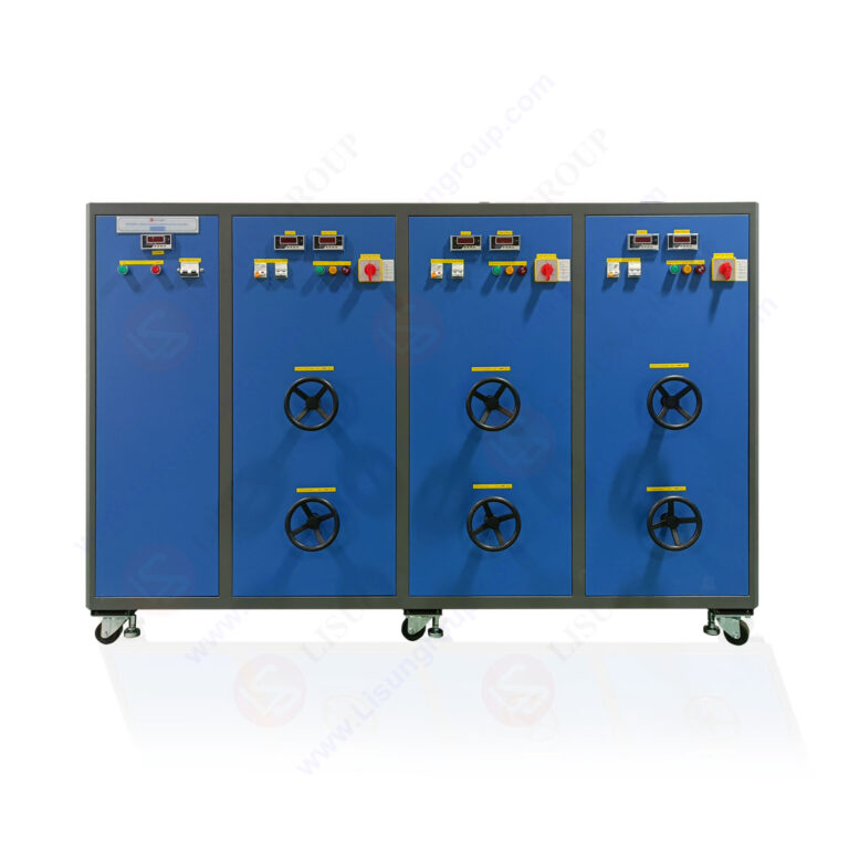
Multi-stage protection includes magnetic circuit breakers on input lines with 10kA interrupting capacity, solid-state overcurrent relays with 2ms response time, and ground fault detection with 30mA sensitivity. Emergency stop circuits comply with IEC 60204-1 requirements, with dual-channel redundant contactors isolating all loads within 20ms of activation. Thermal fuses rated at 110°C provide backup protection for each load element.
5.1 CZKS Series Life Testers Compatibility
The DFX series interfaces directly with LISUN CZKS series switch life testers through dedicated 25-pin D-sub connectors carrying load current, control signals, and status feedback. The CZKS-3A three-channel life tester coordinates with DFX-20-3CH to perform sequential endurance tests on three devices simultaneously, with individual cycle counting and failure detection. Communication protocol uses RS-485 at 115200 baud with Modbus RTU framing for parameter synchronization.
5.2 SW-6 Bending Testers Integration
For cord switch testing per IEC 61058-1, the SW-6 bending tester connects to DFX series load cabinets via 4mm banana jacks with locking collars. The bending tester applies 10,000 flex cycles while the load cabinet maintains specified current and power factor. Real-time resistance monitoring identifies conductor strand breakage as resistance increases exceeding 10% of initial value. This combination enables comprehensive cord switch qualification within single test setups.
6.1 Factory Calibration Procedures
Each DFX unit undergoes 72-hour burn-in at rated current with power factor cycling between 0.3 and 0.9 lagging every 30 minutes. Calibration uses reference current shunts with 0.01% accuracy and precision voltage dividers with 0.005% ratio tolerance. Power factor calibration employs a six-port network analyzer traceable to national metrology institutes. Calibration certificates include measurement uncertainty budgets per ISO/IEC 17025 guidelines.
6.2 Field Verification Methods
Monthly verification uses portable load standards with ±0.1% resistance tolerance and ±0.5% inductance tolerance. Test procedures include measuring 20 calibration points per channel across the load range, with acceptance criteria of ±1% deviation for voltage and current, ±0.02 for power factor. Annual recalibration recommended for accredited laboratories, with factory service providing ISO/IEC 17025 certified calibration at the LISUN facility.
7.1 Dimmer Switch Testing Configuration
For electronic dimmer compliance with IEC 60669-2-1, the DFX series configures capacitive loads of 47µF to 100µF in series with inductive loads of 50mH to 100mH, simulating compact fluorescent lamp inputs. Power factor settings between 0.5 and 0.8 lagging replicate dimmer-phase control conditions. Voltage measurement bandwidth of 5kHz captures phase-cut waveforms for analysis of leading-edge and trailing-edge dimmer operation.
7.2 Relay Endurance Test Setup
Electromechanical relay testing per IEC 61810-1 requires load currents up to 30A with power factor 0.6 lagging. The DFX-40 model provides 40A capability with 0.01 power factor resolution, enabling relay contact force calculations. Auxiliary contacts on the life tester monitor relay operation timing with 1ms resolution, detecting contact bounce durations exceeding 5ms as failure events.
The LISUN DFX series Externally Ballasted Fluorescent Lamp Test Load Cabinet delivers precision load simulation for IEC 60598 compliance testing across electrical accessory certification laboratories. With five models spanning 20A to 80A current ranges, power factor adjustment from 0.3 to 0.9 lagging, and measurement accuracy within ±0.5%, the equipment meets requirements of IEC 60669-1 Clause 19.2, IEC 60884-1 Clause 20, and IEC 61058-1 standards. Integration with CZKS life testers and SW-6 bending testers creates comprehensive testing workstations for switches, connectors, and relays. Thermal management systems with forced air and water-cooled options enable continuous operation at rated loads, while multi-stage protection ensures both sample integrity and operator safety. For quality control engineers and third-party testing facilities, the DFX series provides reliable, reproducible load simulation with documented calibration traceability. The equipment reduces certification cycles through simultaneous multi-channel operation and automated data logging, supporting laboratories in maintaining ISO/IEC 17025 accreditation requirements.
Q1: What is the difference between DFX-20 and DFX-20-3CH models for switch testing?
A: The DFX-20 provides a single channel with 20A output, suitable for testing one switch at a time. The DFX-20-3CH offers three independent channels, each capable of 20A output simultaneously. This allows testing three switches concurrently, reducing total test time for high-volume certification programs. Each channel on the DFX-20-3CH has independent power factor adjustment and thermal protection, enabling different load conditions per channel. For laboratories performing 10,000-cycle endurance tests on multiple switch samples, the three-channel model can complete three tests in the same time as one test on the single-channel unit. Both models maintain ±0.5% current accuracy and support the same power factor range of 0.3 to 0.9 lagging. The DFX-20-3CH requires 380VAC input while the DFX-20 operates on standard 220VAC, which may influence power distribution requirements.
Q2: How does the DFX series maintain stable power factor across extended test cycles?
A: Power factor stability is achieved through temperature-controlled inductive components with iron-powder cores that exhibit minimal permeability drift below 100°C. The capacitance bank uses polypropylene film capacitors with temperature coefficients of ±50ppm/°C, ensuring capacitance variation below 0.5% across 25°C to 55°C ambient ranges. Active compensation circuitry samples reactive power every 100ms and adjusts inductor tap positions through solid-state relays if power factor deviates by more than 0.01 from setpoint. For long-duration tests exceeding 8 hours, the system performs automatic recalibration at 2-hour intervals by briefly isolating load elements and comparing measured impedance with stored calibration values. This maintains power factor within ±0.02 of setpoint over 72-hour continuous operation, meeting the stability requirements of IEC 60669-1 Annex B for endurance testing.
Q3: Can the DFX series be integrated with existing laboratory automation systems?
A: Yes, the DFX series supports multiple integration interfaces. RS-485 communication with Modbus RTU protocol allows connection to programmable logic controllers or laboratory information management systems. Ethernet option provides TCP/IP connectivity for remote monitoring via web browsers. The equipment includes a 20-contact auxiliary relay interface for status signaling to external automation controllers, indicating load active, fault condition, or test completion states. Analog output signals of 0-10V correspond to current and voltage measurements for connection to data acquisition systems. Software development kits provide LabVIEW and Python libraries for custom automation scripts. The electrical accessory load tester can be fully automated, with test sequences programmed to switch between multiple load configurations without operator intervention, essential for 24-hour endurance testing programs according to IEC certification requirements.
Q4: What maintenance procedures are recommended for maintaining DFX series calibration accuracy?
A: Weekly visual inspection checks for discolored load elements indicating overheating, secure connection terminals, and unobstructed cooling fans. Monthly verification involves measuring known reference loads using external calibration standard resistors and inductors, with logging of deviations. Quarterly cleaning removes dust from air intakes and fan blades using compressed air at 20PSI maximum. Semi-annually, all relay contacts should be exercised through 10 full-range switching cycles to prevent oxide buildup. Annual professional calibration at LISUN or accredited laboratory verifies all 128 power factor settings within ±0.01 accuracy. The calibration process includes thermal imaging of load banks under full rated current to identify hot spots indicating degradation. Proper maintenance ensures the ballasted lamp load simulator maintains IEC 60598 compliance verification capability throughout its service life.
Q5: How does the DFX-80 model handle thermal dissipation at 80A continuous current?
A: The DFX-80 employs hybrid cooling combining forced air and water circulation. Four 120mm fans rated at 180CFM total flow cool resistive load elements mounted on aluminum fins with 2.5m² surface area. Inductive loads use liquid-cooled copper windings with deionized water circulation at 6L/min flow rate. A closed-loop chiller maintains water temperature at 25°C ±2°C entering the load cabinet. Thermal sensors at 48 locations monitor element temperatures, triggering current reduction if any point exceeds 80°C. The cabinet’s thermal mass of 45kg aluminum heatsink provides 20-minute thermal buffer for short overcurrent conditions. For 80A continuous testing, the system achieves thermal equilibrium at 65°C max temperature, allowing 24-hour endurance tests without interruption. This design enables electrical product certification testing at maximum load conditions per IEC 60598-1 Clause 12 requirements.