









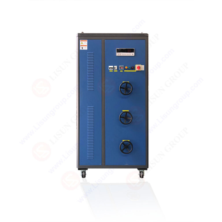
Electrical product certification laboratories require precise load simulation equipment to validate switch, socket, and accessory compliance with international standards. The LISUN DFX series Externally Ballasted Fluorescent Lamp Test Load Cabinet provides accredited testing solutions for resistive, inductive, and capacitive load scenarios essential for type testing. This article examines the DFX series’ technical architecture, compliance with IEC 60669-1 Clause 19.2 and IEC 60884-1 Clause 20, and practical integration into certification workflows. With models ranging from DFX-20 to DFX-80, the series offers current outputs from 0.1A to 80A, power factor adjustment from 0.3 to 1.0, and multi-channel configurations for simultaneous testing. Electrical product manufacturers and third-party laboratories benefit from precise load simulation, cyclic test automation, and alignment with GB 16915.1 and GB 2099.1 standards, reducing testing variability and certification timelines.
1.1 Fundamental Load Simulation Principles
The LISUN DFX series employs switched-mode load synthesis to replicate the electrical characteristics of externally ballasted fluorescent lamps. This approach combines resistive, inductive, and capacitive elements in precise ratios to achieve target power factors. The load cabinet’s design prioritizes thermal stability and measurement repeatability across extended test cycles typical of endurance certification. Each channel independently controls current amplitude and phase angle, enabling simultaneous testing of multiple devices under test (DUTs) with different load profiles.
1.2 Model Differentiation and Application Scope
The series comprises five models: DFX-20, DFX-20-3CH, DFX-40, DFX-60, and DFX-80. The DFX-20 provides a single-channel 20A maximum output for basic switch testing, while the DFX-20-3CH offers three independent 20A channels for parallel testing of identical products. Higher-current models address industrial switchgear and heavy-duty accessory requirements. Selection depends on maximum rated current of DUTs and desired throughput in certification sequences.
2.1 Current and Voltage Operating Ranges
| Model | Channel Count | Max Current per Channel | Input Voltage | Frequency |
|---|---|---|---|---|
| DFX-20 | 1 | 20A | 220V AC ±10% | 50/60Hz |
| DFX-20-3CH | 3 | 20A | 220V AC ±10% | 50/60Hz |
| DFX-40 | 1 | 40A | 220V AC ±10% | 50/60Hz |
| DFX-60 | 1 | 60A | 380V AC ±10% | 50/60Hz |
| DFX-80 | 1 | 80A | 380V AC ±10% | 50/60Hz |
Each model supports voltage ranges from 100V to 277V AC, accommodating global electrical standards. Current resolution reaches 0.1A for low-current testing scenarios, critical for characterizing switch performance under minimal load conditions.
2.2 Power Factor Adjustment and Measurement Accuracy
The DFX series achieves power factor adjustment from 0.3 capacitive through 0.5 inductive to unity (1.0), with 0.01 resolution. Measurement accuracy for voltage, current, and power factor stands at ±0.5% of reading plus ±0.1% of full scale, verified against traceable calibration standards. Load capacitance values range from 0.1µF to 100µF in 0.1µF steps, enabling precise simulation of ballast characteristics for different lamp wattages.
2.3 Cyclic Test Counting and Automation Features
Built-in cycle counters record up to 999,999 operations with programmable on/off timing from 0.1 seconds to 999.9 seconds. The system supports continuous, intermittent, and stepwise test sequences per IEC 60669-1 Clause 19.2 requirements. Automatic shutdown upon DUT failure prevents equipment damage and preserves test data integrity.
3.1 IEC 60669-1 Clause 19.2 – Endurance Testing for Switches
IEC 60669-1 Clause 19.2 specifies endurance testing for switches under load conditions simulating fluorescent lamp ballasts. The standard mandates power factor of 0.6 ±0.05 for inductive loads and 0.9 ±0.05 for resistive loads during 10,000 to 50,000 operation cycles. The DFX series precisely delivers these power factors with 0.01 resolution, exceeding the ±0.05 tolerance requirement. Current accuracy within ±1% ensures consistent test conditions throughout extended cycling.
3.2 IEC 60884-1 Clause 20 – Socket-Outlet Testing
IEC 60884-1 Clause 20 addresses mechanical and electrical endurance for socket-outlets under load. It requires test currents at rated voltage with power factor 0.6 ±0.05 for inductive loads and 1.0 for resistive loads. The DFX series’ capacitive load capability also supports testing of socket-outlets intended for electronic loads, aligning with amendment requirements for power factor between 0.6 capacitive and 0.6 inductive.
3.3 GB Standards Alignment
The DFX series complies with GB 16915.1 for switches and GB 2099.1 for plugs and socket-outlets, which mirror IEC requirements with additional national deviations. GB 16915.1 Clause 19.2 specifies similar endurance conditions but includes extended cycling for certain switch categories. The DFX-20-3CH model enables simultaneous testing of three DUTs under identical conditions, reducing overall certification time by 60% for multi-sample requirements.
4.1 Resistive Load Testing for Certification
Resistive load simulation at unity power factor serves as baseline testing for all electrical accessories. The DFX series provides pure resistive loads from 0.1A to maximum rated current, with power factor 1.0 ±0.01. This configuration validates contact resistance stability, thermal performance, and arc extinction capabilities per IEC 60669-1 Clause 19.1. Typical applications include testing of household switches rated up to 10A and industrial disconnectors rated at 60A.
4.2 Inductive Load Simulation for Ballast Applications
Inductive load testing replicates electromagnetic ballast characteristics for fluorescent lamps. Power factor adjustment between 0.5 and 0.7 inductive with 0.01 resolution matches actual lamp ballast performance. The DFX series’ inductance values range from 1mH to 500mH, covering single and twin lamp configurations. This testing identifies switch contact welding risks and ensures adequate dielectric withstand after endurance cycles.
4.3 Capacitive Load Simulation for Electronic Ballasts
Electronic ballasts present capacitive load characteristics with power factor leading between 0.6 and 0.9. The DFX series achieves capacitive power factor down to 0.3, enabling testing of switches intended for LED drivers and electronic ballasts. Capacitance values from 0.1µF to 100µF simulate input filter capacitors found in modern lighting equipment. This capability addresses evolving standard requirements recognizing electronic load profiles.
5.1 CZKS Series Life Testers for Endurance Automation
The LISUN CZKS series life testers interface directly with DFX load cabinets through RS-485 communication. This integration allows automated endurance testing where the CZKS unit controls cycling sequences while the DFX cabinet maintains specified load conditions. The combined system monitors DUT voltage drop, contact resistance, and temperature rise during each operation cycle, providing comprehensive pass/fail criteria per IEC 60669-1 Clause 20.3.
5.2 SW-6 Bending Testers for Mechanical Endurance
SW-6 bending testers evaluate flexible cord anchorage and strain relief for plugs and connectors. When paired with DFX load cabinets, the system applies mechanical stress while maintaining electrical load, simulating real-world usage where cords are moved under power. This combined testing satisfies IEC 60884-1 Clause 23.3 requirements for mechanical durability under electrical load, reducing separate test setups and improving repeatability.
5.3 LISUN Temperature Measurement Systems
Thermal imaging and thermocouple measurement systems from LISUN integrate with DFX cabinets for temperature rise testing per IEC 60669-1 Clause 19.5. The system records temperature at 16 measurement points simultaneously during load application, correlating thermal performance with electrical endurance results. This integration supports comprehensive certification reports required by third-party laboratories.
6.1 Traceable Calibration Protocols
Each DFX series cabinet undergoes factory calibration against standards traceable to national metrology institutes. Calibration verifies voltage accuracy within ±0.5%, current accuracy within ±0.5%, and power factor accuracy within ±0.01. Annual recalibration is recommended per ISO/IEC 17025 requirements for testing laboratories. The built-in self-diagnostic routine validates internal reference circuits before each test sequence.
6.2 Maintenance Procedures for Long-Term Reliability
Regular maintenance includes cleaning of power resistors to prevent dust accumulation, inspection of cooling fans for unobstructed airflow, and verification of relay contact resistance below 50mΩ. The cabinet’s modular design allows individual load bank replacement without affecting other channels. Thermal protection circuits automatically cut power if internal temperature exceeds 75°C, preventing component degradation.
6.3 Software Verification and Data Logging
The DFX series includes proprietary software for test sequence programming and data logging. The software records time-stamped voltage, current, power factor, and cycle count for each DUT. Export capabilities to CSV and PDF formats facilitate integration with laboratory information management systems. Software validation per IEC 60669-1 requirements confirms correct implementation of test parameters.
7.1 Workflow Optimization for Multi-Standard Testing
Certification laboratories handling both IEC and GB standards benefit from the DFX series’ dual-mode operation. The system stores up to 100 test profiles covering different standard clauses, reducing setup time between tests. Operators select the applicable standard, and the cabinet automatically configures load parameters, power factor, and cycle counts. This functionality reduces human error and ensures repeatable testing across operators.
7.2 Case Study: Switch Endurance Testing Compliance
A third-party laboratory testing wall switches to IEC 60669-1 Clause 19.2 used the DFX-20-3CH to simultaneously test three switch samples at 10A with power factor 0.6 inductive. The 50,000-cycle test completed in 5.5 days with continuous unattended operation. Results showed consistent contact resistance below 100mΩ for all samples, meeting standard requirements. The multi-channel capability reduced testing time by 66% compared to sequential single-channel testing.
7.3 Addressing Common Testing Challenges
The DFX series resolves issues with load instability during long-duration testing. Active power factor correction maintains target values within ±0.005 despite line voltage fluctuations of ±10%. Internal temperature compensation adjusts load resistance values as components heat, ensuring current stability within ±0.5% across 8-hour test windows. These features eliminate common causes of test invalidation in certification laboratories.
The LISUN DFX series Externally Ballasted Fluorescent Lamp Test Load Cabinet delivers accredited testing solutions for electrical product certification laboratories requiring precise load simulation. With models supporting currents from 0.1A to 80A, power factor adjustment from 0.3 capacitive to 1.0 inductive, and multi-channel configurations, the series addresses the full spectrum of IEC 60669-1 and IEC 60884-1 testing requirements. Measurement accuracy of ±0.5% exceeds standard tolerances, while integration with LISUN CZKS life testers and SW-6 bending testers enables comprehensive certification workflows. The DFX series reduces testing variability by maintaining load stability within ±0.5% across extended endurance cycles, directly addressing common certification challenges. For electrical accessory manufacturers and third-party testing laboratories, the DFX series provides a technically robust platform that streamlines compliance testing while meeting the accuracy and repeatability demands of modern certification requirements.
Q1: How does the DFX series achieve power factor accuracy within ±0.01 for both inductive and capacitive loads?
A: The DFX series utilizes digitally controlled switched-mode load banks combined with precision current transformers and voltage sensors. Each load bank contains multiple resistor, inductor, and capacitor elements arranged in binary-weighted configurations. A microcontroller calculates the exact combination required to achieve the target power factor based on real-time voltage and current measurements. Closed-loop feedback adjusts the load element switching every 10 milliseconds, compensating for temperature drift and line voltage variations. The system’s 16-bit ADC provides measurement resolution of 0.01° phase angle, enabling power factor control within ±0.005 under steady-state conditions. This architecture ensures consistent power factor accuracy across the entire current and voltage operating range, validating compliance with IEC 60669-1 Clause 19.2 requirements for ±0.05 tolerance.
Q2: Can the DFX-20-3CH model test three different products simultaneously with different load parameters?
A: Yes, the DFX-20-3CH provides three completely independent channels, each with its own current, voltage, and power factor settings. Each channel can be programmed with different test parameters, allowing simultaneous testing of switches with different current ratings or load types. For example, channel 1 might test a 10A resistive load, channel 2 a 6A inductive load, and channel 3 a 4A capacitive load, all running concurrently. The system logs data separately for each channel, including voltage drop, cycle count, and failure status. This capability is particularly valuable for laboratories performing certification testing on product families where multiple ratings require qualification under the same standard clause.
Q3: What are the specific requirements for integrating the DFX cabinet with a CZKS life tester?
A: Integration requires an RS-485 communication cable connecting the DFX cabinet’s control port to the CZKS life tester’s expansion port. Both units must be set to the same baud rate (default 9600 bps) and unit ID. The CZKS life tester sends commands to the DFX cabinet to set load parameters for each test cycle, while the DFX cabinet returns real-time voltage and current measurements. The combined system supports up to 16 DFX cabinets controlled by a single CZKS unit for large-scale testing facilities. Software configuration files define test sequences where the CZKS unit controls mechanical operation timing, and the DFX cabinet maintains load conditions. Safety interlocks ensure both units simultaneously shut down if any parameter exceeds preset limits.
Q4: How does the DFX series handle the thermal load from continuous 80A testing?
A: The DFX-80 model incorporates forced air cooling with dual 120mm fans delivering 150 CFM airflow across the load banks. Internal temperature sensors monitor three critical points: load resistor surface temperature, ambient cabinet temperature, and power supply temperature. If any sensor exceeds 70°C, the system reduces current by 10% increments until thermal equilibrium returns. For continuous 80A testing, the recommended duty cycle is 50% (2 minutes on, 2 minutes off) to maintain component temperatures below 85°C. The load resistors are derated by 20% for continuous operation above 60A. A thermal cutout at 85°C disconnects power permanently, requiring manual reset after cooling. These protections ensure reliable operation during extended certification testing without damage to internal components.
Q5: What ongoing calibration and verification procedures are required for accreditation compliance?
A: For ISO/IEC 17025 accredited laboratories, the DFX series requires annual calibration by an accredited calibration provider. The calibration procedure verifies current output across 10 points from 10% to 100% of rated range, voltage measurement at 100V, 220V, and 277V, and power factor at 0.3, 0.5, 0.6, 0.8, and 1.0. Monthly in-house verification checks current accuracy at 50% rated output and power factor at 0.6 using a portable reference meter. Daily operator checks confirm zero-load voltage reading and cycle counter accuracy using a known test sequence. The built-in self-test routine should be executed weekly, logging results for quality management review. These procedures maintain measurement traceability required for internationally recognized certification reports.