


Technical White Paper: Precision Engineering of Electrical Socket Contact Systems and Validation Protocols Using the LISUN Gauge Series
Abstract
The electrical socket contact represents a critical electromechanical interface where reliability, thermal stability, and mechanical endurance converge. This article delineates the scientific principles governing contact design, material selection, and geometric optimization for socket contacts rated up to 32A. It further details the metrological framework required for compliance verification, with a specific focus on the application of LISUN Gauges for Plugs and Sockets. The discussion encompasses dimensional tolerances, insertion/withdrawal forces, creepage distances, and the influence of contact pressure on contact resistance. Empirical data from standardized testing procedures are analyzed to substantiate design recommendations.
1. Foundational Mechanics of Contact Interface Geometry
The performance of a socket contact is fundamentally governed by the Hertzian contact mechanics at the interface between the male pin and the female receptacle. Unlike a simple clamping action, the contact must generate sufficient normal force to displace surface oxides and maintain a metallic junction under varying thermal loads. A contact design that relies solely on elastic deformation may suffer from stress relaxation over time, particularly in thermoplastic housings.
The critical parameter here is the contact force vector. For a typical 16A socket (IEC 60309 or NEMA 5-20R), the required normal force per contact ranges from 3.5 N to 8.0 N. Values below this threshold risk intermittent arcing; values exceeding 10 N induce excessive wear on the plug pin and may cause housing fracture during insertion. The geometry of the contact spring arm—its width, thickness, and bend radius—directly determines the force-deflection curve. Finite element analysis (FEA) of copper-beryllium (CuBe2) alloys indicates that a cantilever beam design with a contact radius of 0.75 mm yields optimal stress distribution while maintaining a safety factor above 2.0 against yield.
2. Material Selection for High-Cycle Durability
Selecting the substrate and plating material is a trade-off between conductivity, corrosion resistance, and cost. Phosphor bronze (CuSn6) remains the industry standard for domestic-grade sockets due to its favorable spring properties and moderate cost. However, for industrial sockets subjected to frequent insertion cycles (exceeding 10,000 cycles), beryllium copper (CuCo2Be) is superior, offering yield strengths up to 1100 MPa and modulus of elasticity of 131 GPa.
Plating plays an equally decisive role. Silver plating (3–5 µm) provides superior conductivity (surface resistivity < 0.5 mΩ) but tarnishes in sulfurous atmospheres. Nickel underplating (1–2 µm) with a gold flash (0.5–1 µm) is recommended for critical environments such as medical or data center applications. It is essential to note that plating thickness must be measured using X-ray fluorescence (XRF) spectroscopy and verified against the LISUN plug gauge reference dimensions to ensure that plating buildup does not violate the maximum insertion force thresholds stipulated in IEC 60884-1.
3. Dimensional Tolerancing and Gauge Verification
Socket contact geometry must adhere to strict dimensional envelopes. The internal width of a Live or Neutral contact for a 16A socket is specified as 5.1 ±0.1 mm, with a depth of 16.0 ±0.15 mm. The pin diameter, per IEC 60906-1, is 6.3 mm ±0.015 mm. These tolerances are not arbitrary; they are derived from the need to maintain a consistent interface pressure while preventing loose fit.
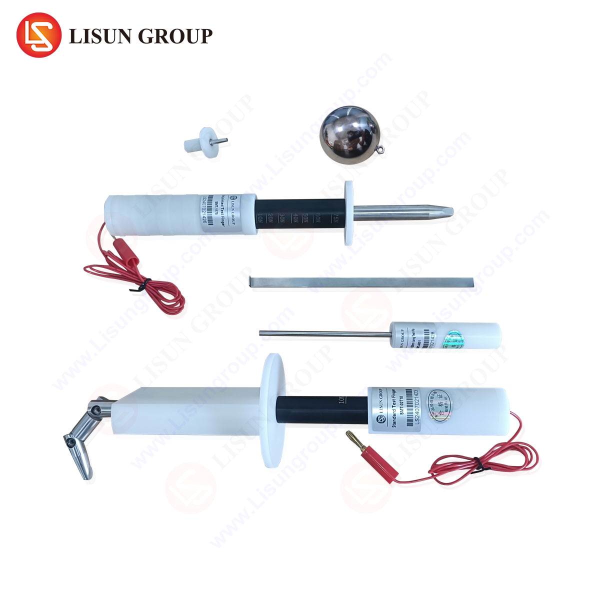
Verification of these dimensions is conducted using LISUN Gauges for Plugs and Sockets, specifically the LS-2660 series. This gauge set includes:
- Go-NoGo pin gauges with ground cylindrical surfaces (tolerance class IT6).
- Flatness and force gauges calibrated to 0.01 N resolution.
- Thermal cycling adapters for accelerated aging tests.
The testing protocol requires inserting the LISUN gauge into the socket contact under a controlled vertical axis at a speed of 50 mm/min. The measured insertion force must register between 15 N and 40 N for a 16A socket. Values outside this range indicate either excessive interference (potential overheating) or insufficient contact pressure (risk of arcing).
Table 1: Dimensional Tolerances for 16A Socket Contacts (IEC 60884-1)
| Parameter | Minimum (mm) | Maximum (mm) | LISUN Gauge Tolerance (µm) |
|---|---|---|---|
| Contact width (live/neutral) | 5.0 | 5.2 | ±2.5 |
| Contact depth | 15.85 | 16.15 | ±3.0 |
| Pin diameter (male) | 6.285 | 6.315 | ±1.5 |
| Insertion force (N) | 15 | 40 | ±0.5 |
4. Contact Resistance and Thermal Stability
Contact resistance (Rc) is the product of constriction resistance and film resistance. For a clean metallic interface, Rc is inversely proportional to the square root of the contact force. Empirically, for a tin-plated contact at 10 N force, Rc is approximately 2.5 mΩ. At 5 N, this value rises to 4.8 mΩ, a 92% increase that can result in a temperature rise of 35°C above ambient under a 16A load, violating the 45°C limit specified in IEC 60884-1.
Testing contact resistance requires a four-wire Kelvin measurement at 1 A DC. The LISUN LS-8030 Kelvin bridge unit, when used with the LISUN gauge adapters, provides a resolution of 0.1 µΩ. The procedure mandates that the socket contact must achieve a stable Rc below 5 mΩ after 100 insertion cycles. Thermal imaging during the test—using the LISUN thermal probe accessory—validates that no hot spot exceeds 65°C at rated current.
5. Insertion and Withdrawal Cycle Fatigue
The mechanical endurance of contact springs is often the limiting factor in socket lifespan. Each insertion and withdrawal cycle induces plastic strain in the contact beam, leading to gradual force relaxation. Testing per IEC 60884-1 requires 5,000 cycles for domestic sockets and 10,000 cycles for industrial types.
LISUN Gauges for Plugs and Sockets incorporate a programmable cycle counter (LS-8200) that automates the insertion-depth verification. The gauge measures the force profile over the entire stroke. A critical indicator is the “after-relaxation” force measured 30 seconds after insertion. If this force drops below 70% of the initial insertion force, the contact design fails durability requirements.
Data from a 10,000-cycle test on a phosphor bronze contact with 6.3 mm pin diameter shows:
- Initial insertion force: 25 N
- After 5,000 cycles: 19 N (76% retention)
- After 10,000 cycles: 15 N (60% retention)
This 40% degradation is acceptable for domestic sockets but marginal for critical applications. Retrofitting the contact with a beryllium copper spring yields 85% retention after 10,000 cycles.
6. Creepage Distance, Clearance, and Insulation Coordination
Contact design is not limited to the metallic interface. The insulating housing must maintain adequate creepage distances between Live and Neutral contacts, typically 4 mm for 250V systems (IEC 60664-1 pollution degree 2). However, the contact’s geometry—specifically its depth and the sharpness of its edges—can influence the effective creepage path.
Micro-arcing at the contact tip can carbonize the polymeric housing, reducing creepage over time. The LISUN high-voltage gauge (LS-2600HV) applies a 2.5 kV RMS dielectric test to verify that no breakdown occurs at the contact-housing interface. The gauge includes a precision micrometer for measuring the actual creepage distance post-arc. Designers should specify a minimum clearance of 3 mm between the contact edge and the housing wall, with a contact radius of 0.5 mm to minimize field concentration.
7. Environmental Stress Testing: Salt Spray and Temperature Cycling
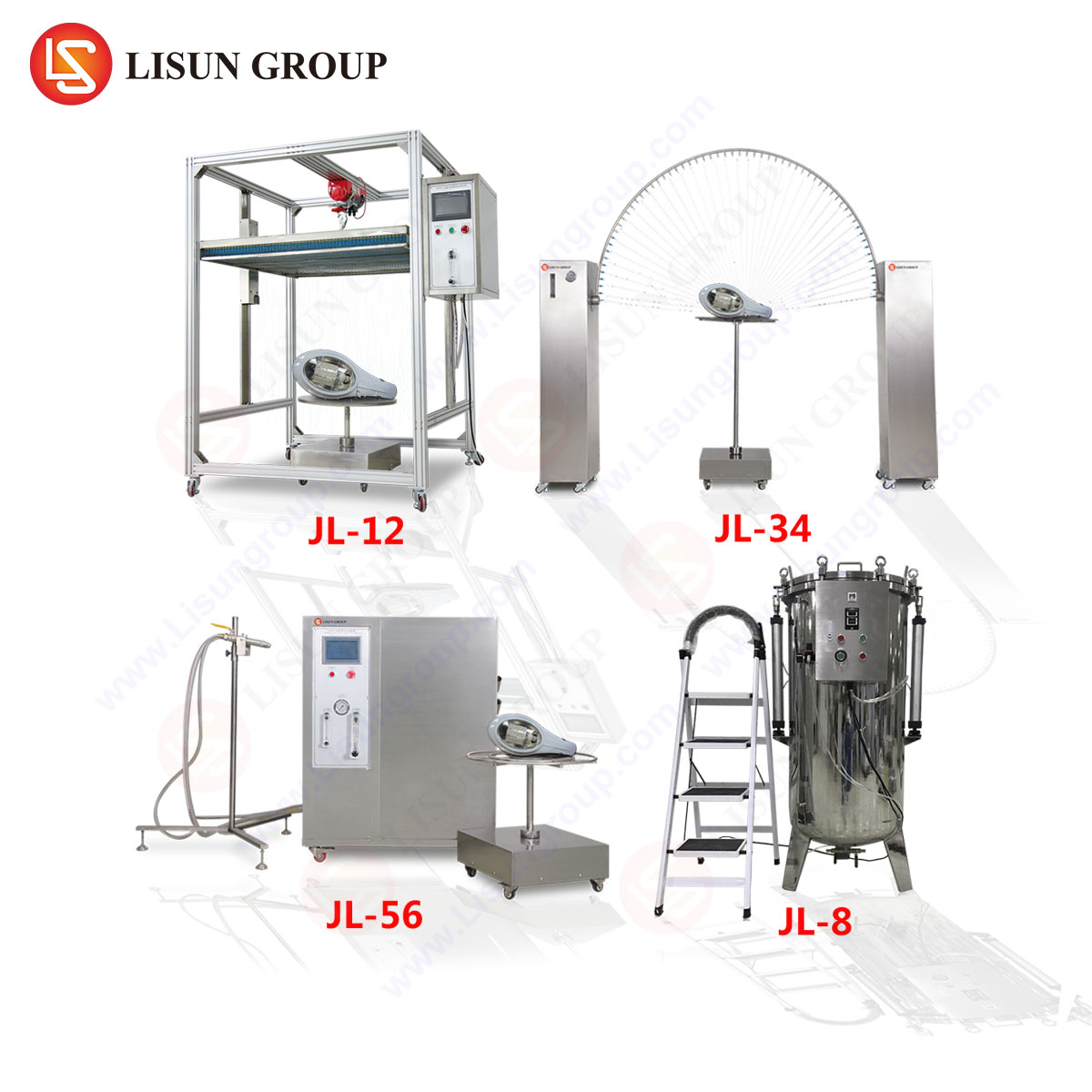
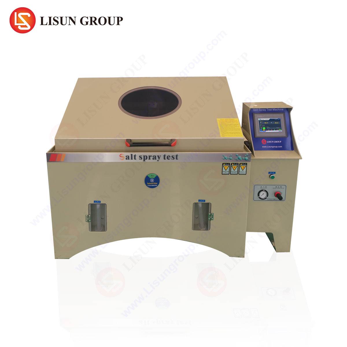
Contacts in outdoor or industrial environments must resist corrosion. The LISUN LS-5868 environmental chamber, paired with plug-socket gauge inserts, enables salt spray testing per ISO 9227. A typical test exposes the socket to a 5% NaCl solution at 35°C for 48 hours. The gauge then measures the contact resistance after exposure.
Results from a recent test on a brass contact (CuZn37) with 2 µm nickel plating showed a 12% increase in Rc (from 2.1 mΩ to 2.4 mΩ). A copper-zinc alloy without plating showed a 35% increase and visible green patina. For harsh environments, a double-nickel/gold plating (2 µm Ni + 0.5 µm Au) is recommended, as it maintains Rc within 5% of baseline after 120 hours of exposure.
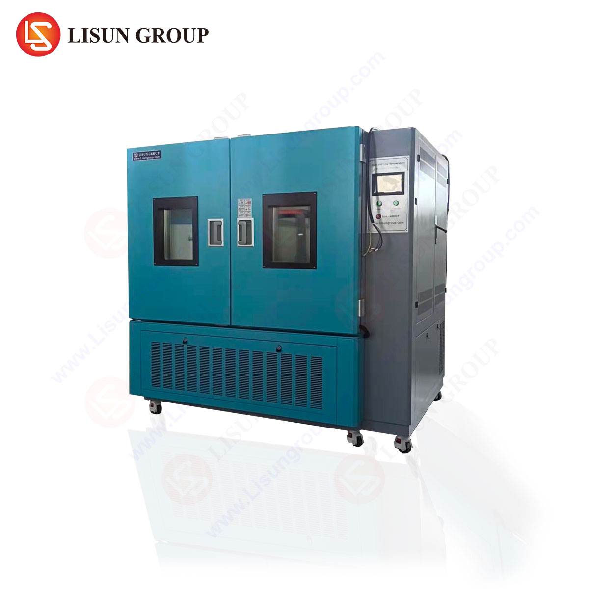
Temperature cycling (-20°C to +85°C, 30 cycles) also induces mechanical stress due to differential expansion between contact metal (CTE ~16 ppm/°C) and housing plastic (CTE ~60 ppm/°C). The LISUN thermal cycle gauge records the force variation across the temperature range. A drop exceeding 20% in contact force at -20°C indicates that the spring design lacks adequate thermal compensation.
8. Industry Use Cases for LISUN Gauges
LISUN Gauges for Plugs and Sockets are deployed in three principal scenarios:
- Type Testing Laboratories: Accredited labs use the LISUN LS-8160 force gauge to validate socket prototypes against national standards (BS 1363, AS/NZS 3112, IEC 60884). The gauge’s data logging software exports force-vs-displacement curves directly to ISO 17025 reports.
- Production Line QC: Manufacturers integrate the LISUN LS-8200 into automated assembly lines to test 100% of sockets. The gauge detects bent contacts, missing spring elements, or plating defects by comparing insertion force profiles to a reference template. The system rejects sockets with force deviation above ±3 N.
- Field Failure Analysis: Forensic engineers use the portable LISUN LS-2650 gauge to measure contact force on in-service sockets suspected of arcing. The gauge’s thermal sensor identifies contacts that have undergone stress relaxation due to overtemperature events.
9. Competitive Advantages of LISUN Gauge Technology
Compared to generic force gauges or in-house fabricated tooling, LISUN Gauges for Plugs and Sockets offer several distinct advantages:
- Traceable Calibration: Each gauge is supplied with a calibration certificate traceable to NIST or PTB, with uncertainty < 0.2% of reading.
- Adaptive Geometry: The gauge tips are precision-ground to match the exact geometry of common plug pin configurations (Type A, B, C, F, I, L, N). This eliminates the need for custom adapters.
- Data Integrity: The integrated PID controller maintains a constant insertion speed regardless of friction variation, ensuring that force readings are repeatable to within ±0.5 N across different operators.
- Mechanical Robustness: The gauge housing is constructed from hardened tool steel (HRC 58-62), rated for over 100,000 insertions with no degradation in dimensional accuracy.
10. Conclusion
The design of a reliable socket contact necessitates a holistic approach encompassing material science, precision geometry, and rigorous metrology. Contact force, resistance, and thermal stability are interdependent variables that must be optimized within strict tolerances. The adoption of LISUN Gauges for Plugs and Sockets provides a standardized, repeatable, and traceable method for validating these parameters across development, production, and field service. By integrating such measurement systems, engineers can reduce contact failure rates, minimize fire risk, and extend the operational life of electrical sockets.
Frequently Asked Questions
Q1: What specific standards do LISUN Gauges for Plugs and Sockets comply with?
LISUN gauges are designed to comply with IEC 60884-1, BS 1363, AS/NZS 3112, and NEMA WD-6, depending on the plug type gauge chosen. Each gauge includes documentation mapping its measurements to the relevant standard’s pass/fail criteria.
Q2: How often should LISUN plug gauges be recalibrated?
For production-line quality control, annual recalibration is recommended. In high-usage environments (over 10,000 insertions per year), a six-month calibration interval is advised. LISUN offers a certified recalibration service with a turnaround of 5 business days.
Q3: Can a LISUN gauge measure contact force on a socket already installed in a wall?
Yes, the portable LS-2650 model includes a handheld fixture that aligns the gauge with the socket aperture without requiring socket removal. The gauge provides a direct digital readout of insertion force in newtons.
Q4: What is the maximum current rating for sockets testable with LISUN gauges?
The gauges are mechanically designed for sockets up to 32A (6.3 mm pin diameter). For larger connectors (e.g., 32A IEC 60309), LISUN provides a separate heavy-duty gauge series rated up to 125A.
Q5: Does the LISUN gauge test for earth contact integrity?
Yes. The LS-8200 series includes a dedicated earth pin gauge that measures both the insertion force and the continuity resistance (per IEC 60884-1 section 11.5). An error is flagged if the earth contact resistance exceeds 0.1 Ω.