









Abstract
The LISUN DFX series externally ballasted fluorescent lamp test load cabinet provides precise electrical accessory load simulation for compliance testing of switches, relays, and controllers. This article examines the DFX-20, DFX-20-3CH, DFX-40, DFX-60, and DFX-80 models, detailing their current output ranges, channel configurations, and power factor adjustment capabilities. The externally ballasted lamp load validation process ensures alignment with IEC 60669-1 and IEC 60884-1 requirements for resistive, inductive, and capacitive load testing. Engineers in manufacturing and third-party laboratories will gain technical insights into load simulation accuracy, cyclic testing protocols, and integration with complementary LISUN equipment for comprehensive electrical accessory evaluation.
1.1 Principles of Ballasted Load Testing
Externally ballasted fluorescent lamp circuits contain inductive ballasts that introduce phase shifts between voltage and current waveforms. The LISUN DFX series replicates these characteristics using precision resistive and inductive components arranged in parallel configurations. This load simulation method allows testing of switches under realistic electrical stress conditions. The power factor of fluorescent lighting circuits typically ranges from 0.45 to 0.85 lagging, depending on ballast design and whether power factor correction capacitors are present. Engineers must replicate these conditions to validate contact performance, arc suppression, and thermal behavior of the device under test (DUT).
1.2 Regulatory Context for Load Testing
International standards mandate specific load testing protocols for electrical accessories. IEC 60669-1 Clause 19.2 defines the test circuits for switches controlling fluorescent lighting loads, specifying voltage, current, and power factor parameters. Similarly, IEC 60884-1 Clause 20 addresses sockets and outlets with associated load requirements. The DFX series load cabinets facilitate compliance by generating stable, repeatable load conditions across multiple test channels. The ability to verify power factor settings before testing ensures traceability of results and defensible compliance documentation.
2.1 Model Configuration and Output Capabilities
The DFX series encompasses five models engineered for different testing scales:
| Model | Current Output Range (A) | Channels | Input Requirement | Power Factor Range |
|---|---|---|---|---|
| DFX-20 | 0.1 – 20 | 1 | AC 220V/50Hz | 0.4 – 1.0 |
| DFX-20-3CH | 0.1 – 20 | 3 | AC 220V/50Hz | 0.4 – 1.0 |
| DFX-40 | 0.1 – 40 | 1 | AC 220V/50Hz | 0.4 – 1.0 |
| DFX-60 | 0.1 – 60 | 1 | AC 220V/50Hz | 0.4 – 1.0 |
| DFX-80 | 0.1 – 80 | 1 | AC 220V/50Hz | 0.4 – 1.0 |
Higher current models enable testing of industrial-grade switches and contactors. The DFX-20-3CH three-channel configuration supports simultaneous testing of multiple accessory samples, reducing total validation time.
2.2 Load Impedance and Power Factor Control
Precision resistors and inductors within the cabinet allow incremental adjustment of load characteristics. The power factor can be tuned in 0.01 resolution steps, enabling engineers to match specific ballast parameters. Capacitive compensation networks in selected models simulate circuits with power factor correction capacitors, whose leading power factors create distinct arcing and current interruption behaviors. Measurement instruments integrated into the cabinet provide real-time voltage, current, and power factor readings with accuracy ratings of ±0.5% for voltage and ±1% for current.
3.1 IEC and GB Standard Requirements
The DFX series is designed to satisfy multiple compliance frameworks:
| Standard | Applicable Clause | Test Parameter | DFX Capability |
|---|---|---|---|
| IEC 60669-1 | Clause 19.2 | Fluorescent lamp load, PF 0.6 lagging | Independent PF adjustment |
| IEC 60669-2-1 | Clause 20 | Electronic switches with lamp loads | Stable current regulation |
| IEC 60884-1 | Clause 20 | Socket-outlet load testing | Continuous load cycling |
| GB 16915.1 | Clause 19 | Domestic switch load simulation | Multiple channel options |
The externally ballasted lamp load validation approach satisfies both European harmonized standards and Chinese national standards, allowing manufacturers to certify products for global markets with a single test setup.
3.2 Verification Protocol for Load Accuracy
Before initiating compliance testing, engineers must verify that the load cabinet produces the required electrical conditions. The DFX series incorporates built-in calibration routines that compare displayed values against internal reference measurements. For third-party laboratories requiring external validation, the cabinet includes test points for connecting traceable measurement instruments. This dual verification approach ensures that test results withstand regulatory scrutiny and audit review processes.
4.1 Cyclic Endurance Testing
Switches undergo mechanical and electrical endurance tests specified at 10,000 to 50,000 operations, depending on the accessory type and rating. The DFX series supports continuous operation with automatic cycle counting and programmable on/off timing sequences. During each cycle, the switch interrupts the ballasted load current, generating an arc that degrades contact surfaces. The load cabinet maintains consistent current and power factor throughout the test duration, ensuring that all cycles subject the DUT to identical stress conditions.
4.2 Abnormal Operation and Fault Simulation
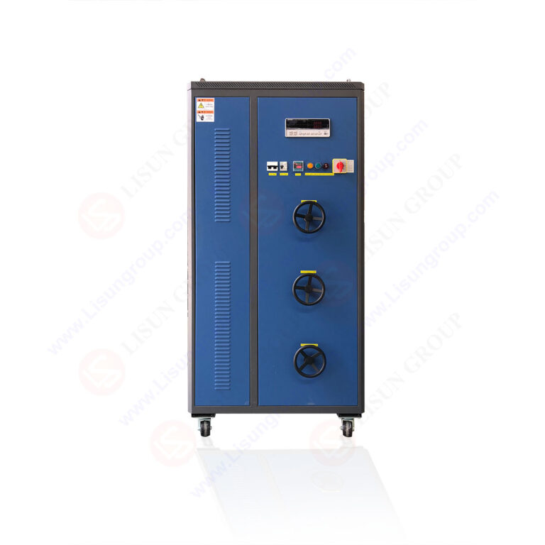
Standards require testing under abnormal conditions including locked-rotor scenarios and overload currents. The DFX-60 and DFX-80 models deliver current outputs up to 80 A, enabling simulation of fault-level conditions beyond normal rated operation. Engineers can program current ramps and step changes to evaluate protective functions and failure modes. Although the primary focus remains externally ballasted lamp load validation, the current range flexibility supports auxiliary testing of motor loads and resistive heating circuits.
5.1 Integration with LISUN Testing Systems
The DFX series integrates seamlessly with other LISUN products to build comprehensive test benches:
| Complementary Equipment | Function | Integration Benefit |
|---|---|---|
| CZKS-1/CZKS-3 Life Testers | Mechanical/electrical life cycling | Auto-cycle coordination with load application |
| SW-6 Bending Testers | Cord flexing and strain relief testing | Sequential testing protocols |
| Temperature Measurement Systems | Thermal monitoring of DUT and contacts | Real-time temperature data collection |
This ecosystem approach enables testing laboratories to automate complete qualification programs without manual intervention between test phases.
5.2 Sample Fixture and Wiring Considerations
Connection between the load cabinet and the DUT requires consideration of cable impedance and connection stability. The DFX series provides output terminals rated for continuous current at the maximum model specification, with mounting arrangements compatible with standard test enclosures. For three-channel operation, isolated wiring prevents cross-channel interference that could skew measurement results. Earthing and shielding arrangements comply with IEC 61010-1 safety requirements for laboratory electrical equipment.
6.1 Power Factor and Current Stability
Stability testing of the load cabinet itself is essential to maintain confidence in test results. The DFX series maintains current output within ±1% of set point under steady-state conditions, with transient response settling within 0.5 seconds after load changes. Power factor stability remains within ±0.02 of the configured value across the full operating range. These specification limits are documented in factory calibration certificates traceable to national metrology institutes.
6.2 Temperature Rise Considerations
High-current testing generates significant heat within load resistors and inductors. The DFX series implements forced air cooling and thermal protection circuits that interrupt testing if cabinet temperatures approach component limits. This thermal management extends component service life and maintains load characteristic stability during extended test runs. For continuous 24-hour testing protocols, the cabinet’s duty cycle rating ensures uninterrupted operation.
7.1 Application-Driven Model Selection Criteria
| Testing Application | Recommended Model | Justification |
|---|---|---|
| Single-sample basic compliance | DFX-20 | Adequate current range, lower footprint |
| Multi-sample production validation | DFX-20-3CH | Parallel testing of identical samples |
| Industrial switch certification | DFX-40 | Enhanced current capability |
| High-current contactor testing | DFX-60 | 60 A output for heavy-duty accessories |
| Extreme current scenario simulation | DFX-80 | Maximum current flexibility |
7.2 Cost and Operational Efficiency Analysis
For testing laboratories handling diverse product categories, the DFX-20-3CH provides operational efficiency benefits through simultaneous testing of three samples, reducing total validation time by up to 60% compared to sequential single-channel testing. The higher-current models represent incremental investments justified when manufacturers regularly test industrial-grade accessories requiring currents above 20 A. All models share common operational interfaces, minimizing training requirements for laboratory technicians switching between different cabinet configurations.
The LISUN DFX series offers a technically robust solution for externally ballasted lamp load validation, satisfying the demanding load simulation requirements of IEC 60669-1, IEC 60884-1, and related international standards. With models ranging from 20 A to 80 A and the versatile DFX-20-3CH three-channel configuration, laboratories can configure testing systems that match their exact product qualification needs. The ±0.01 power factor resolution and high current stability enable reproducible test conditions essential for compliance evidence. Integration with CZKS life testers and SW-6 bending testers creates comprehensive automated workflows that improve laboratory throughput. For electrical accessory manufacturers and third-party testing facilities, the DFX series delivers the precision load simulation, regulatory alignment, and operational efficiency required to support rigorous product certification programs. By maintaining electrical parameters within tight tolerance bands across thousands of operation cycles, the DFX series provides a dependable foundation for electrical safety validation and international market access.
Q1: What is the primary difference between the DFX-20 and DFX-20-3CH models for externally ballasted lamp load validation?
A: The DFX-20 provides a single test channel with current output from 0.1 A to 20 A, suitable for sequential testing of individual accessory samples. The DFX-20-3CH incorporates three independent channels, each capable of the same 20 A output range, enabling simultaneous testing of three DUTs under identical load conditions. This parallel configuration significantly reduces total test time for production quality assurance programs. Each channel functions independently with separate current adjustment, allowing different test scenarios to run concurrently. The three-channel model is particularly advantageous in high-volume manufacturing environments where throughput directly impacts production costs. Both models maintain the same power factor range and accuracy specifications.
Q2: How does the DFX series ensure stable power factor during extended cyclic testing?
A: The DFX series achieves power factor stability through precision-wound inductors with controlled temperature coefficients and low-resistance contactors that minimize heat generation. During operation, internal sensors monitor load current and voltage phase relationships, providing real-time readings on the digital display. When testing protocols require adjustment for different ballast characteristics, engineers can modify the power factor setting to the desired value, which is maintained within ±0.02 accuracy. For externally ballasted lamp load validation, the inductive component is carefully matched to typical fluorescent ballast specifications, ensuring that reactive current precisely replicates field conditions. Forced air cooling maintains component temperatures within safe ranges, preventing drift in load characteristics.
Q3: What standards compliance does the DFX series fulfill for lamp load testing?
A: The DFX series is engineered to comply with load requirements specified in IEC 60669-1 Clause 19.2 for switches controlling fluorescent lamp loads, IEC 60669-2-1 Clause 20 for electronic switches, and IEC 60884-1 Clause 20 for socket-outlets. These standards define test voltages, currents, and power factors for evaluating accessory performance under realistic load conditions. The cabinet also aligns with GB 16915.1 Clause 19 requirements for the Chinese market. For laboratories requiring multi-standard validation, the flexible current and power factor adjustment ranges allow configuration to meet various national requirements without hardware modifications.
Q4: Can the DFX-60 or DFX-80 be used for testing loads other than externally ballasted lamps?
A: Yes, the DFX-60 and DFX-80 models provide current ranges up to 60 A and 80 A respectively, accommodating testing of additional load types such as resistive heating elements, motor circuits, and tungsten filament lamps. The load simulation components include both resistive and inductive paths that can be configured to match different load profiles. While externally ballasted lamp load validation remains the primary application focus, the expanded current range increases equipment utilization by enabling a single test cabinet to support multiple product certification programs. This flexibility reduces capital expenditure requirements for testing laboratories that serve diverse client sectors.
Q5: What maintenance procedures are recommended for the DFX series load cabinets?
A: Periodic calibration verification every 12 months ensures continued measurement accuracy for load current, voltage display, and power factor readings. Routine inspection of power connection terminals for signs of arcing or oxidation, cleaning of air filters for the cooling system, and verification of safety interlocks should be performed quarterly. After extensive high-current testing, thermal imaging can identify hot spots requiring attention. The manufacturer provides calibration services and replacement components with detailed service documentation. Maintaining calibration traceability records is essential for laboratories operating under ISO/IEC 17025 quality management requirements, ensuring that all test results remain legally defensible in certification audits.